Dry process for manufacturing hybridized boron fiber/carbon fiber thermoplastic composite materials from a solution coated precursor

a technology of thermoplastic composite materials and boron fibers, which is applied in the direction of adhesive processes with surface pretreatment, coatings, chemical instruments and processes, etc., can solve the problems of difficulty in uniform coating of fibers, and achieve the effect of increasing the center line distance, reducing the applied pressure gradient, and increasing the curvature radius of the bar surfa

Inactive Publication Date: 2003-02-04
NASA
View PDF8 Cites 8 Cited by
  • Summary
  • Abstract
  • Description
  • Claims
  • Application Information

AI Technical Summary

Benefits of technology

Near the exit 224 of the processing component 220 is the impregnation bar assembly 240. Referring now to FIGS. 3A and 3B, the impregnation bar assembly 240 comprises a bar fixture 244, a plurality of bar uprights 242a, 242b, 242c, and a plurality of stationary bars 241a, 241b, 241c fixed substantially perpendicular to the axial direction of the precursor tape, which is represented by the vector 247. Preferably, the number of stationary bars is three and the cross-sectional shape of each bar is substantially triangular. Each bar 241a, 241b, 241c is oriented sequentially in series to the direction 247 of the heated precursor tape having dispersed boron fibers 218. The heated precursor tape having dispersed boron fibers 218 is pulled through the impregnation bar assembly 240 in such a manner as that each bar contacts the heated precursor tape having dispersed boron fibers 218 at a cross-sectional apex 243a, 243b, 243c of each bar. Either sequential pathway of the precursor tape through the bars, under-over-under (shown), or over-under-over (not shown), will produce a good result. The impregnation bar assembly 240 may comprise any appropriate configuration for processing the heated precursor tape 218, preferably comprising an adjustable bar holder 245 which adjusts the height of the middle bar 241b relative to the other two bars 241a and 241c. The height of the middle bar 241b remains stationary during the course of the manufacturing process. Changing the height of the middle bar effectively changes the wrap angle of the impregnation bar assembly 240.
The bars may be constructed of materials which maintain structural integrity at temperatures above the processing temperature of the polymeric matrix of the prepreg material. Some examples of materials which may be used for the bars include: polished quartz, bulk carbon graphite, and ceramic such as partially stabilized zirconia (PSZ). The geometry of the bars and the bar uprights controls the resulting pressure gradients which are applied to the prepreg material by the impregnation bar assembly 240. The geometry can be adjusted to affect the pressure gradients. Examples of such adjustments and the effects include: 1) increasing the bar surface curvature radius decreases the applied pressure gradients; 2) increasing the center line distance between each contact radius center of each stationary bar decreases the applied pressure gradients; 3) increasing the wrap angle defined by the center line and the precursor tape increases the applied pressure gradients. The application of these pressure gradients allows for the expulsion of voids and the re-distribution of the polymeric matrix and the filaments, a process known in the art as wetting-out. This process causes the heated precursor tape having dispersed boron fibers 218 to begin forming into a consolidated, wide, flat shape, creating an initial width.

Problems solved by technology

The disadvantage of thermoplastic polymers as a composite matrix material is the difficulty of uniformly coating the fibers due to the high viscosity of the molten polymer.

Method used


Image

  • Dry process for manufacturing hybridized boron fiber/carbon fiber thermoplastic composite materials from a solution coated precursor
  • Dry process for manufacturing hybridized boron fiber/carbon fiber thermoplastic composite materials from a solution coated precursor
  • Dry process for manufacturing hybridized boron fiber/carbon fiber thermoplastic composite materials from a solution coated precursor

Examples


example 2

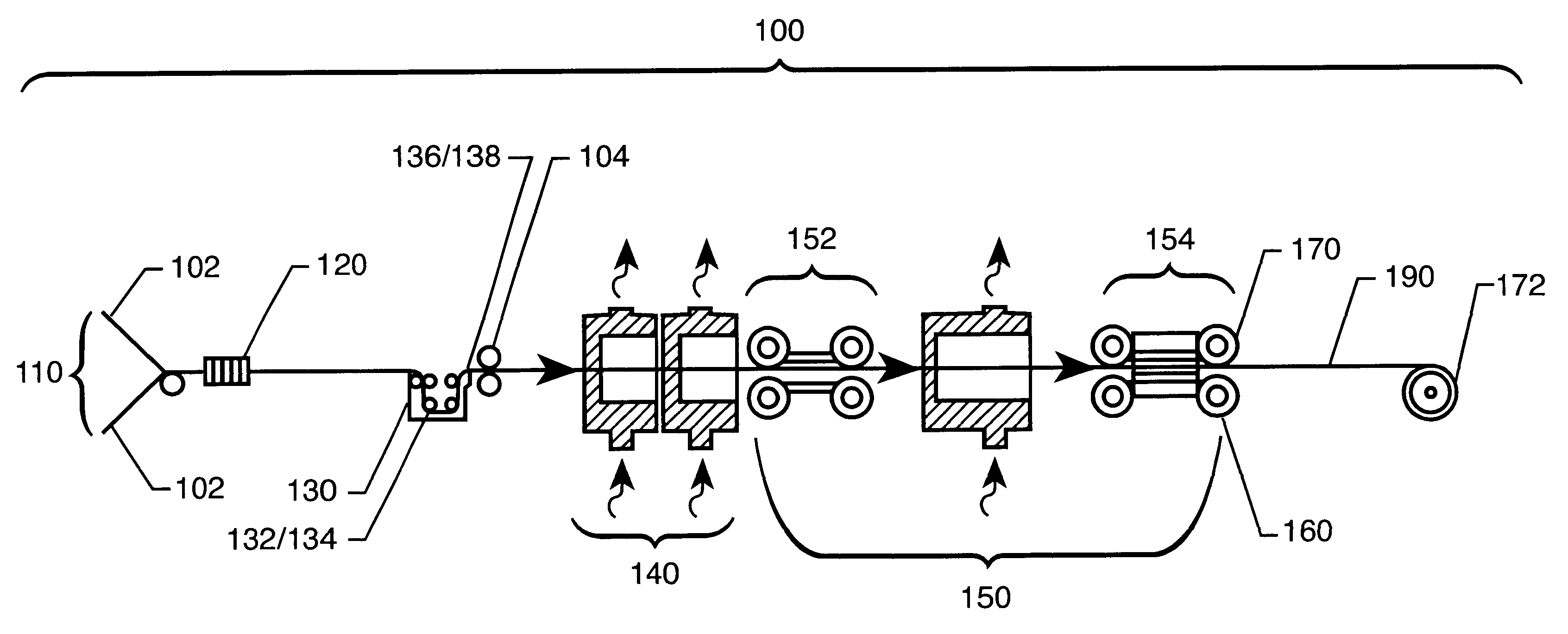
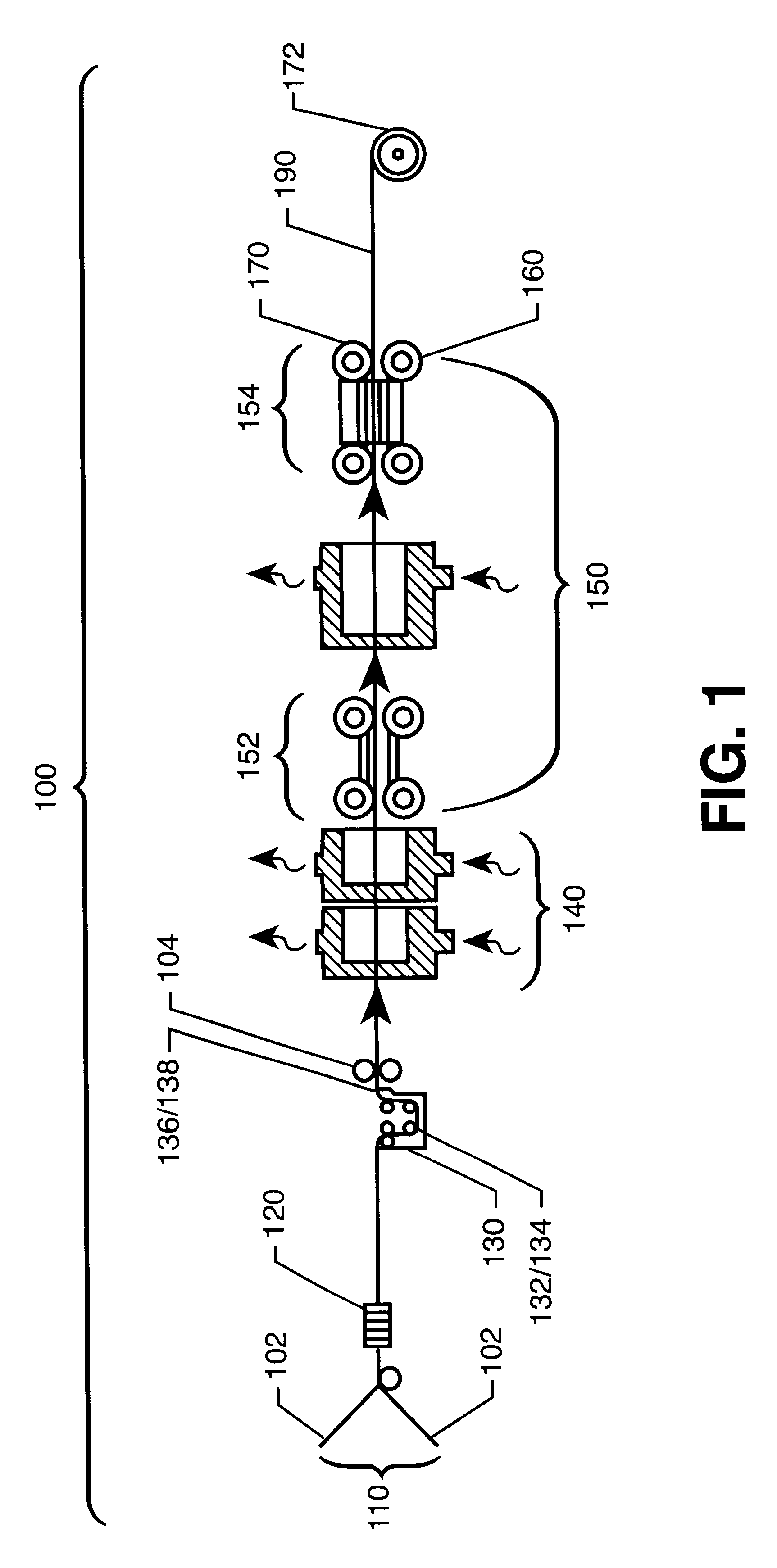
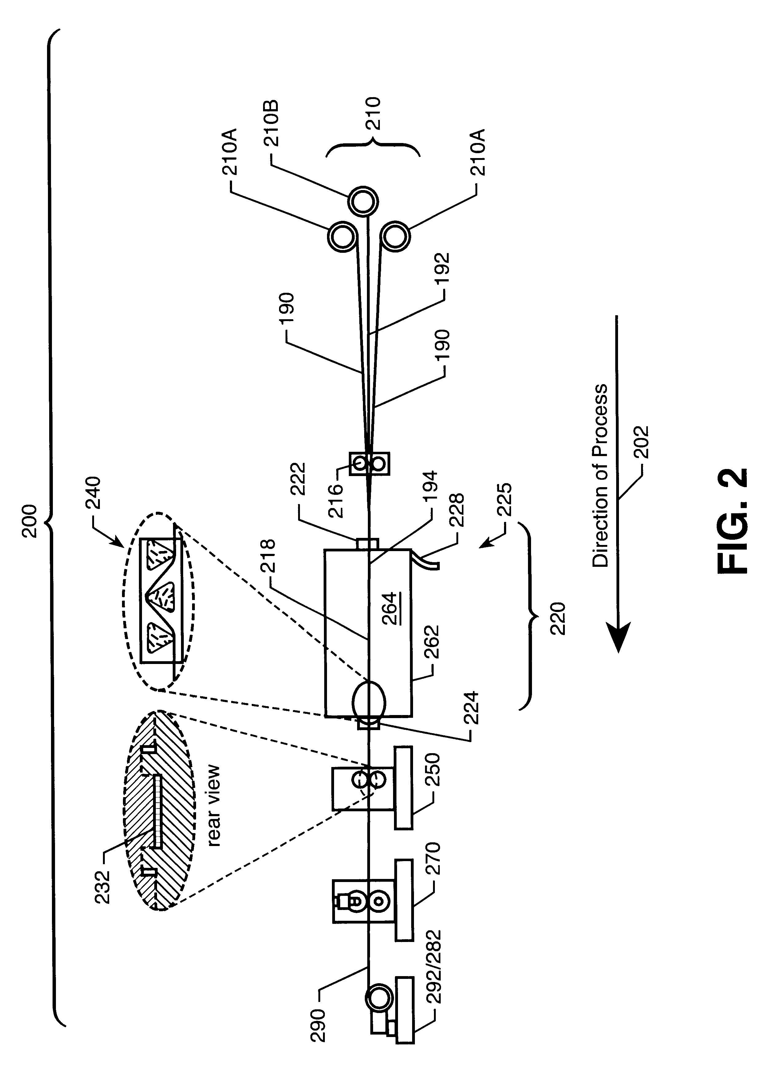
IM7 / IAX solution-coated precursor tape are creelled as illustrated in FIG. 2. The solution-coated precursor has a nominal resin content of approximately 36 wt %. A precursor tape with twenty-six ends is aligned and run into a furnace over a set of stationary bars. Another precursor tape with twenty-six ends is run through the furnace over another set of stationary bars located slightly below the first set. Both sets of bars are set at 400.degree. C. and allowed to equalize for one hour. Collimated boron ends are then run through the furnace between both sets of bars and precursor tapes, becoming encapsulated at the forming nips. The furnace zones are set to provide enough heat to devolitalize, imidized and melt the polymer prior to traversing the bars, and to heat the bars themselves to allow flow and spreading of the precursor tapes as they go over and under the bars. The forming die roller is nitrogen cooled to quench the hybrid tape to a specified shape. The line speed is control...


PUM

PropertyMeasurementUnit
particle sizeaaaaaaaaaa
widthaaaaaaaaaa
widthaaaaaaaaaa

Abstract

An apparatus for producing a hybrid boron reinforced polymer matrix composite from precursor tape and a linear array of boron fibers. The boron fibers are applied onto the precursor tapes and the precursor tape processed within a processing component having an impregnation bar assembly. After passing through variable-dimension forming nip-rollers, the precursor tape with the boron fibers becomes a hybrid boron reinforced polymer matrix composite. A driving mechanism is used to pulled the precursor tape through the method and a take-up spool is used to collect the formed hybrid boron reinforced polymer matrix composite.

Description

ORIGIN OF INVENTIONThis invention described herein was made by employees of the United States Government and may be manufactured and used by or for the Government or government purposes without payment of any royalties thereon or therefor.1. Field of the InventionThis invention relates generally to the preparation and fabrication of prepreg tapes and ribbons and relates specifically to the preparation of polyimide resin / carbon fiber / boron fiber unidirectional solvent-free tape and ribbon having well wet-out and encapsulated boron fiber evenly distributed throughout the tape or ribbon, controlled dimensions and resin content, and composite structures having high mechanical properties.2. Description of the Related ArtReinforcing fibers comprising filaments combined with a matrix resin are known in the art and typically are called "towpregs." A conventional towpreg consists of thousands of filaments impregnated with a continuous mass of matrix. The type of advanced reinforcing fibers t...

Claims


Application Information

Patent Timeline
Patent Type & Authority Patents(United States)
IPC IPC(8): B29B15/10B29B15/12B29C70/04B29C70/50
CPCB29C70/50B29B15/122B29B15/12
Inventor BELVIN, HARRY LCANO, ROBERTO J.
Owner NASA
Why Eureka
Try Eureka