
Mechanical power outputting apparatus and inverter apparatus

a technology inverter, which is applied in the direction of electric generator control, dynamo-electric converter control, electric devices, etc., can solve the problems of increasing the size and cost of difficult for the conventional mechanical power outputting apparatus to drive, and large size and cost of high withstand voltage capacitors

Inactive Publication Date: 2003-02-11
TOYOTA JIDOSHA KK +1
View PDF13 Cites 40 Cited by
  • Summary
  • Abstract
  • Description
  • Claims
  • Application Information

AI Technical Summary

Benefits of technology

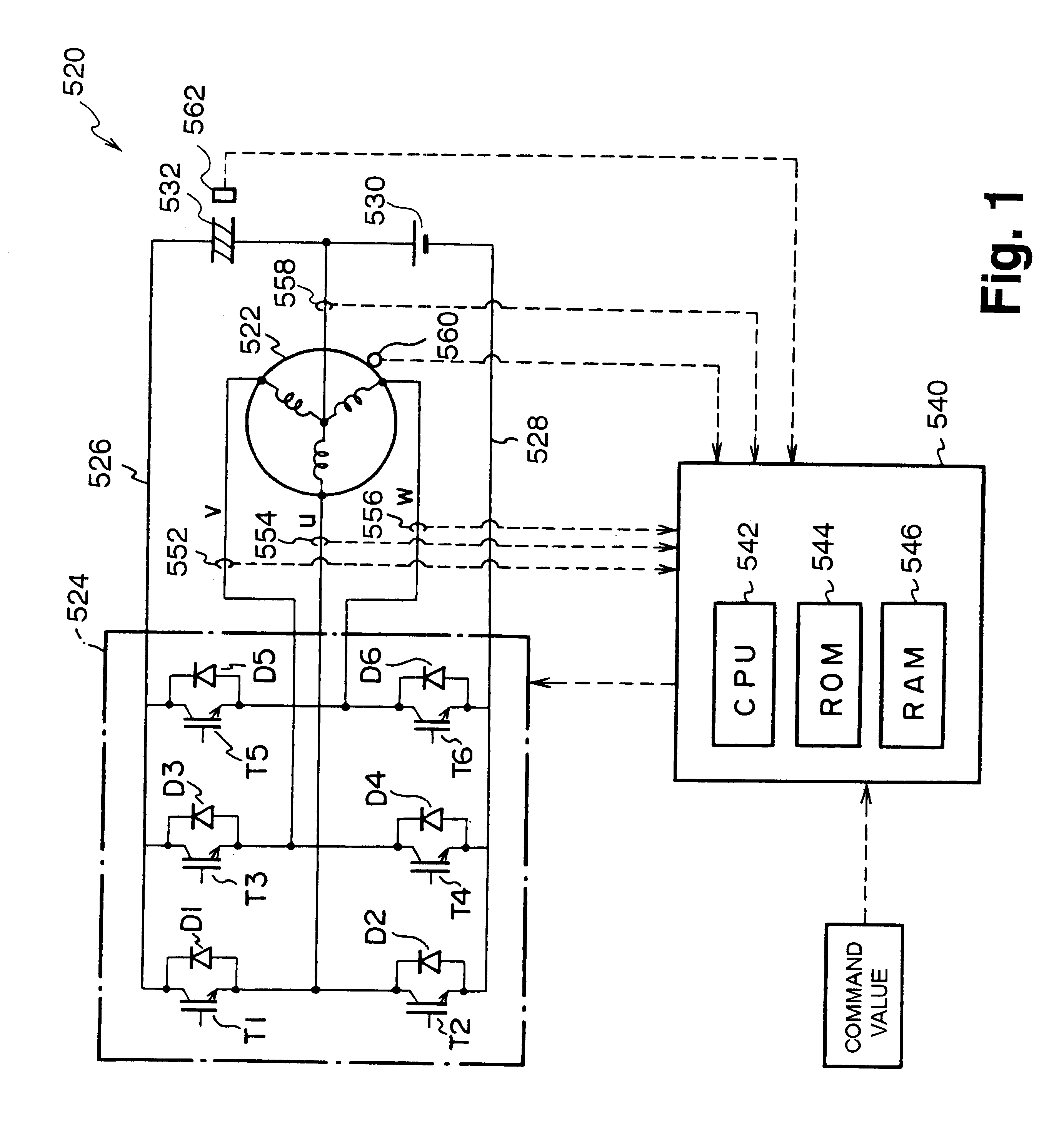
In a mechanical power outputting apparatus of the present invention, an electric power supplying section as a direct-current power supply is connected with either the positive pole bus or the negative pole bus of an inverter circuit, and the electric power supplying section is also connected with the neutral point of a dynamo-electric motor, and a charging section capable of charging and discharging is connected with the other bus between the positive pole bus and the negative pole bus of the inverter circuit that is not connected with the electric power supplying section, and the charging section is also connected with the neutral point of the dynamo-electric motor. Consequently, the electric power supplying section and the charging section connect the positive pole bus and the negative pole bus of the inverter circuit in series, and then it is possible to drive the dynamo-electric motor on the supposition that the electric power supplying section and the charging section are an integrated direct-current power supply. A circuit constituted of the coil of each phase of the dynamo-electric motor and a switching element of each phase of the inverter circuit can charge the charging section by the use of the electric power of the electric power supplying section by means of the switching operation of the switching element, and the charging of the charging section and the driving of the dynamo-electric motor can be performed simultaneously by synchronization of the switching operation with the switching operation at the time of the driving of the dynamo-electric motor. Moreover, because the withstand voltage of the charging section is a value that is a result of the subtraction of the voltage of the electric power supplying section from a voltage necessary for driving the dynamo-electric motor, the withstand voltage of the charging section can be lower than the withstand voltage of a capacitor connected with the positive pole bus and the negative pole bus of the inverter circuit. As a result, the charging section can be realized to be small in size and cheap in cost, namely the mechanical power outputting apparatus can be realized to be small in size and cheap in cost, and further the durability and the stability of the mechanical power outputting apparatus can be improved because the charging section is made to have a low withstand voltage.
According to the mechanical power outputting apparatus of still another aspect of the present invention, a driving current is made to be a pseudo-polyphase alternating current of voltage levels of three steps or more, i.e. voltage levels of a positive voltage, a negative voltage, and an intermediate voltage in between these two, and consequently the probability of the appearance of the zero voltage vector where the voltage of each of the phases are the same voltage, but different from the voltage of a second power supply, can be largely decreased, and the probability of the appearance of current pulsations that can be generated at the neutral point of a dynamo-electric motor can be decreased. As a result, the loss of the dynamo-electric motor can be suppressed.
According to the mechanical power outputting apparatus of a yet another aspect of the present invention, a driving current is made to be a pseudo-polyphase alternating current of voltage levels of three steps or more, and consequently the probability of the appearance of the zero voltage vector, the voltage of each phase of which is the same voltage but different from the voltage of a second power supply, can be largely decreased, and the probability of the appearance of current pulsations that can be generated at the neutral point of a dynamo-electric motor can be decreased. As a result, the loss of the dynamo-electric motor can be suppressed.
According to the mechanical power outputting apparatus of a further aspect of the present invention, the switching of a plurality of switching elements in an inverter circuit is controlled on the basis of the modulated wave of each phase based on the voltage command of each phase of a polyphase alternating current and on the basis of the carrier wave of each phase having a prescribed phase difference between each other corresponding to each phase of the polyphase alternating current, and consequently the probability of the appearance of the zero voltage vector, the voltage of each phase of which is exactly the same voltage but different from the voltage of a second power supply, can be largely decreased, and the probability of the appearance of current pulsations that can be generated at the neutral point of a dynamo-electric motor can be decreased. As a result, the loss of the dynamo-electric motor can be suppressed.
According to the mechanical power outputting apparatus of a still further aspect of the present invention, the switching of a plurality of switching elements in an inverter circuit is controlled on the basis of the modulated wave of each phase based on the voltage command of each phase of a polyphase alternating current and on the basis of the carrier wave of each phase having a prescribed phase difference between each other corresponding to each phase of the polyphase alternating current, and consequently the probability of the appearance of the zero voltage vector the voltage of each phase of which is the same voltage can be decreased, and the probability of the appearance of current pulsations that can be generated at the neutral point of a dynamo-electric motor can be decreased. As a result, the loss of the dynamo-electric motor can be suppressed.

Problems solved by technology

The high withstand voltage capacitor is large in size and high in cost, and further that causes the increase of the size and the cost of the mechanical power outputting apparatus.
Moreover, the conventional mechanical power outputting apparatus can drive a single dynamo-electric motor with the direct-current power supply of a low voltage, but it is difficult for the conventional mechanical power outputting apparatus to drive a plurality of dynamo-electric motors separately with the direct-current power supply of the low voltage.
Moreover, the conventional mechanical power outputting apparatus has a probability of a large current pulsation being generated in the current that flows into or flows out from the neutral point of the dynamo-electric motor to increase the loss of the dynamo-electric motor.

Method used


Image

  • Mechanical power outputting apparatus and inverter apparatus
  • Mechanical power outputting apparatus and inverter apparatus
  • Mechanical power outputting apparatus and inverter apparatus

Examples


embodiment 1

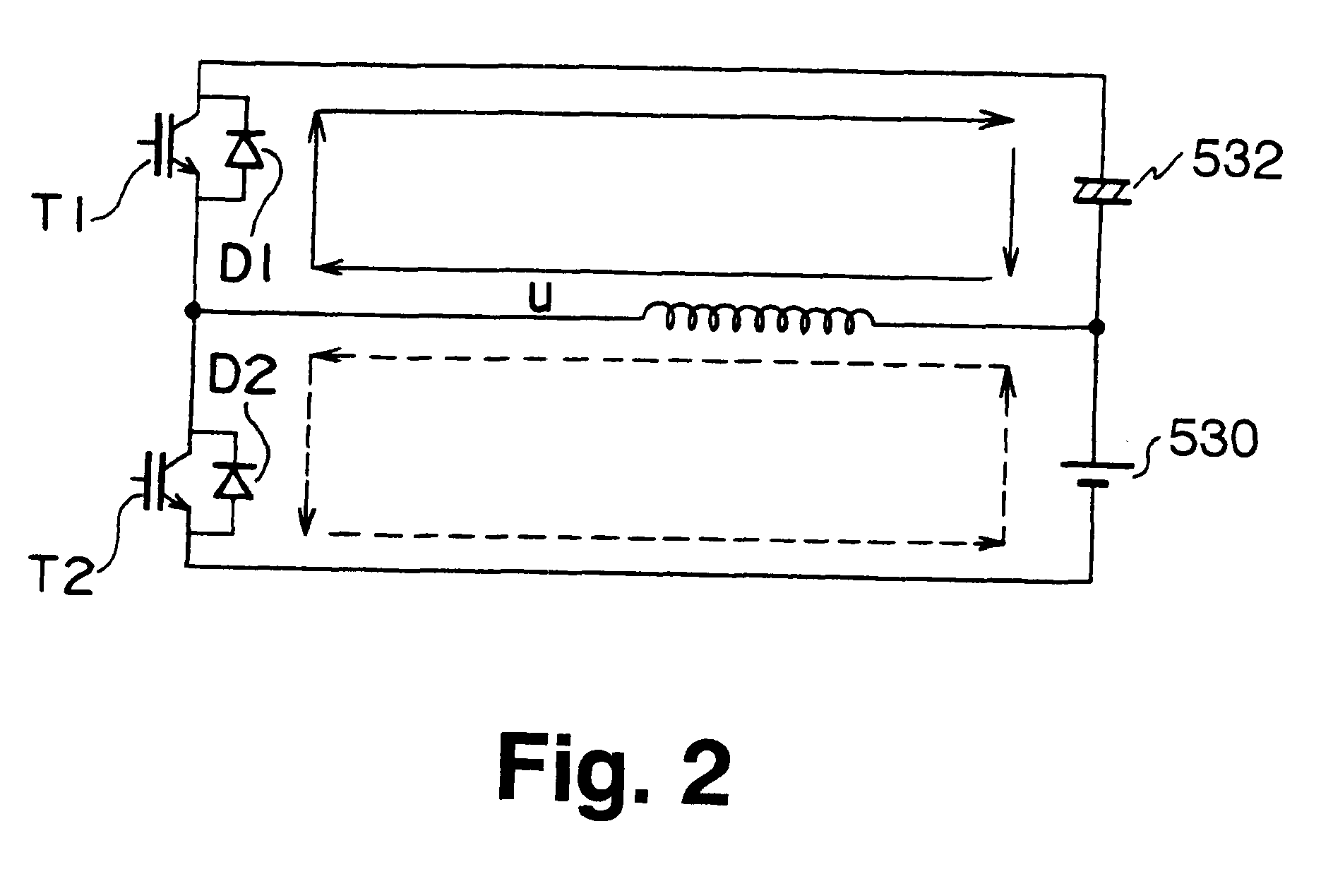
FIG. 2 is the circuit diagram of a part of the mechanical power outputting apparatus 520 of the embodiment 1 when the leakage inductances of the three-phase coils of the motor 522 are featured. Now, when a state in which the transistor T2 is turned on is considered, a short circuit shown by the broken arrows in the figure is formed, and the u-phase of the three-phase coils of the motor 522 functions as a reactor. When the transistor T2 is turned off, the energy that is stored in the u-phase of the three-phase coils that functions as a reactor is stored in the capacitor 532 through the charging circuit shown by the solid arrows in the figure. Consequently, the circuit can be regarded as a chopper circuit for storing the energy of the direct-current power supply 530 in the capacitor 532. Because the v-phase and the w-phase of the three-phase coils of the motor 522 can also be regarded as a chopper circuit like the u-phase thereof, the capacitor 532 can be charged by the execution of t...

embodiment 2

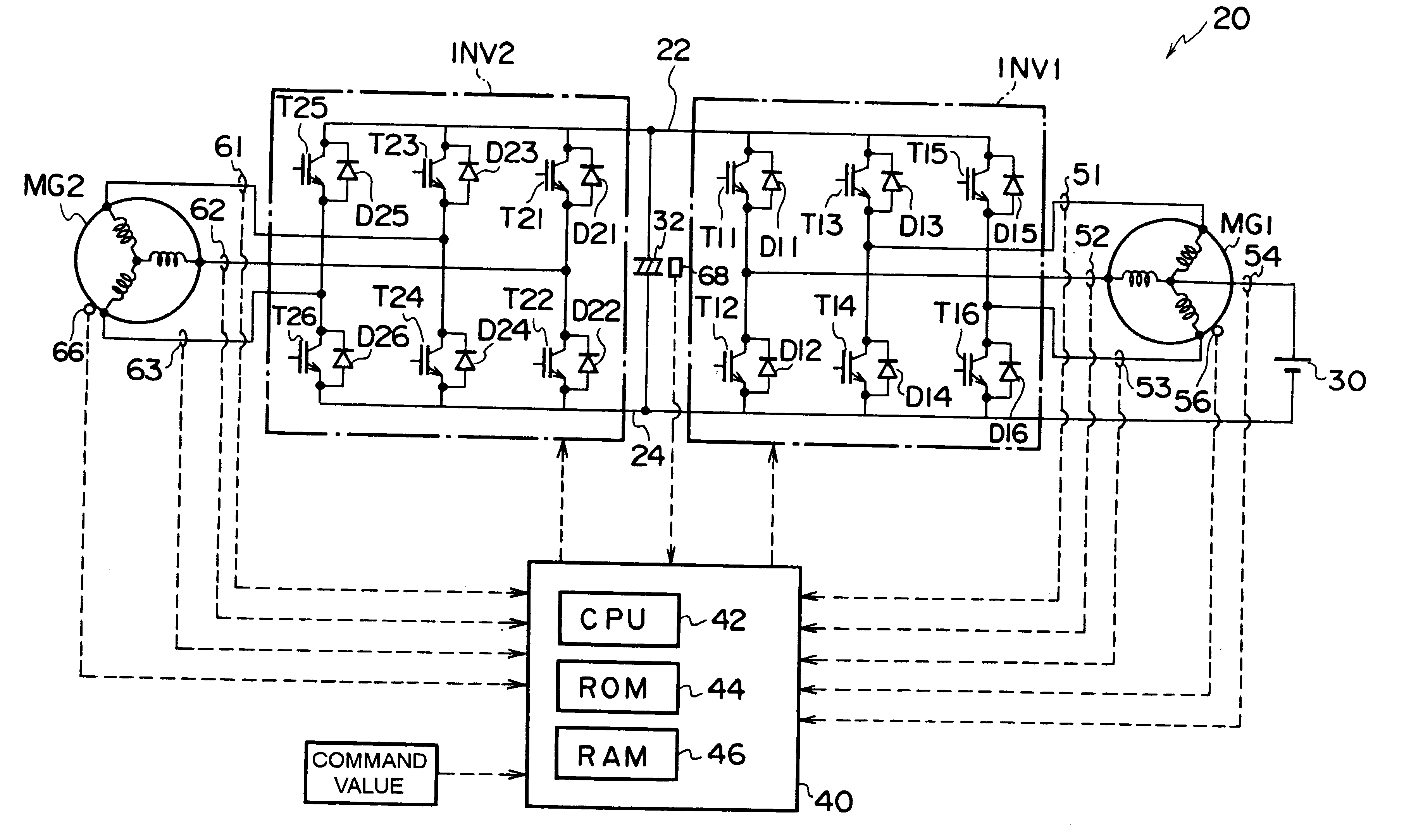
FIG. 6 is a schematic diagram showing the outline of the configuration of the mechanical power outputting apparatus 20 that is the embodiment 2 of the present invention. The mechanical power outputting apparatus 20 of the embodiment 2 comprises, as shown in the figure, a motor MG1 driven to rotate by a three-phase alternating current, an inverter circuit INV1 capable of converting direct-current power into three-phase alternating-current power for supply to the motor MG1, a motor MG2 driven to rotate by a three-phase alternating current, an inverter circuit INV2 capable of converting direct-current power into three-phase alternating-current power for supply to the motor MG2, a direct-current power supply 30 connected between a negative pole bus 24 of the inverter circuit INV1 and the inverter circuit INV2 and the neutral point of the motor MG1, a capacitor 32 connected between a positive pole bus 22 of the inverter circuit INV1 and the inverter circuit INV2 and the negative pole bus...

embodiment 3

Next, the mechanical power outputting apparatus 120 as the embodiment 3 of the present invention will be described. FIG. 12 is the schematic diagram showing the outline of the configuration of the mechanical power outputting apparatus 120 of the embodiment 3. The mechanical power outputting apparatus 120 of the embodiment 3 has the same configuration as that of the mechanical power outputting apparatus of the embodiment 2 other than the disposition of a capacitor 132 as shown in the figure. Accordingly the same constitutional elements of the mechanical power outputting apparatus 120 of the embodiment 3 as those of the mechanical power outputting apparatus 20 of the embodiment 2 are designated by the same reference characters as those of the embodiment 2, and their descriptions are omitted. In the mechanical power outputting apparatus 120 of the embodiment 3, the capacitor 132 is attached so as to connect the positive pole bus 22 of the inverter circuits INV1 and INV2 with the neutra...


PUM


Abstract

A direct-current power supply connecting the negative pole bus of an inverter circuit and the neutral point of a motor and a capacitor connecting the positive pole bus of the inverter circuit and the neutral point of the motor are provided for performing the switching control of the transistors T1-T6 of the inverter circuit on the basis of a phase voltage command value formed by the addition of a direct-current component and an alternating-current component. The voltage between the terminals of the capacitor is controlled on the direct-current component, and the driving control of the motor is performed on the alternating-current component. The supply voltage of the direct-current power supply can be made to be lower than a voltage necessary to drive the motor. Moreover, the withstand voltage of the capacitor can be made to be smaller and the relay circuit can be simplified in comparison with an apparatus equipped with a capacitor connected between the positive pole bus and the negative pole bus of an inverter circuit. As a result, the downsizing of an apparatus and the reduction in costs can be achieved, and the durability and the reliability of the apparatus can be improved.

Description

1. Field of the InventionThe present invention relates to a mechanical power outputting apparatus.2. Description of the Related ArtConventionally, there has been proposed a mechanical power outputting apparatus of this type that is equipped with a capacitor connected with a positive pole bus and a negative pole bus of an inverter circuit that imposes a three-phase alternating current on a dynamo-electric motor, and the mechanical power outputting apparatus is also equipped with a direct-current power supply connected with the positive pole bus or the negative pole bus of the inverter circuit and a neutral point of the dynamo-electric motor (see for example, Japanese Laid-Open Patent Publication No. Hei 10-337047, Japanese Laid-Open Patent Publication No. Hei 11-178114, and the like). The apparatus regards a circuit constituted of the coil of each phase of the dynamo-electric motor and a switching element of each phase of the inverter as a boosting chopper circuit that stores electri...

Claims


Application Information

Patent Timeline
IPC IPC(8): B60K6/00B60K6/04B60L11/18H02P6/08H02P27/04H02P27/08B60K1/02B60K1/00B60K6/365B60K6/46B60L50/15B60L50/16B60W10/08
CPCB60K6/46B60L11/123B60L11/14B60L15/025B60W10/08H02P6/08H02P27/08B60K6/365B60K1/02Y10S903/91B60L2220/14Y02T10/6217Y02T10/643Y02T10/7022Y02T10/7077B60L50/61B60L50/16Y02T10/62Y02T10/64Y02T10/70Y02T10/7072
Inventor SASAKI, SHOICHISHAMOTO, SUMIKAZUKOMATSU, MASAYUKIMORIYA, KAZUNARIOHTANI, HIROKIINAGUMA, YUKIO
Owner TOYOTA JIDOSHA KK
Learn More