Dry clean method instead of traditional wet clean after metal etch

Inactive Publication Date: 2003-03-04
PROMOS TECH INC +2
View PDF18 Cites 77 Cited by
  • Summary
  • Abstract
  • Description
  • Claims
  • Application Information

AI Technical Summary

Problems solved by technology

However, attempts made using microwave power and the above combination gas mixture does not remove sidewall polymer layer 20 well

Method used


Image

  • Dry clean method instead of traditional wet clean after metal etch
  • Dry clean method instead of traditional wet clean after metal etch
  • Dry clean method instead of traditional wet clean after metal etch

Examples


Embodiment Construction

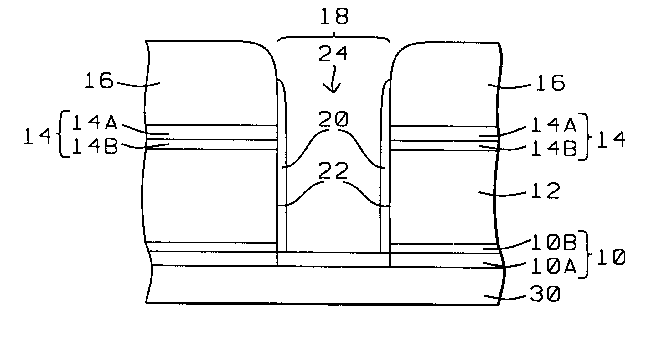
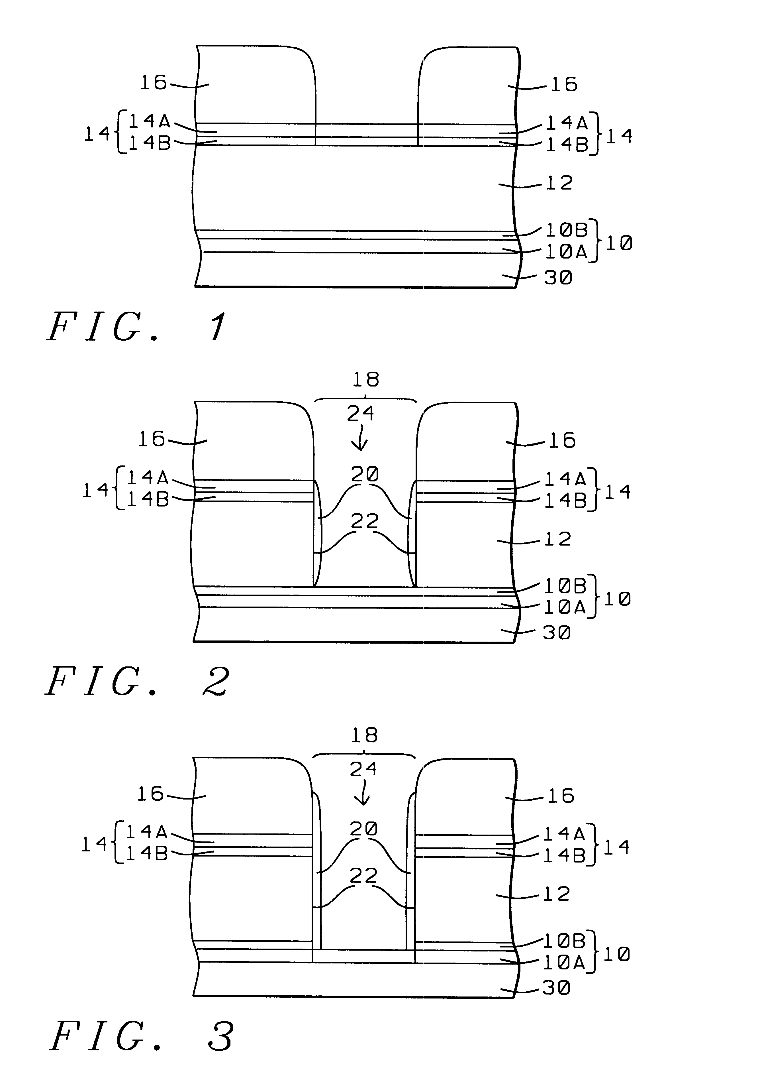
The inventors have discovered that removing the polymer layer 20 requires the use of a two step process (Step I and Step II):

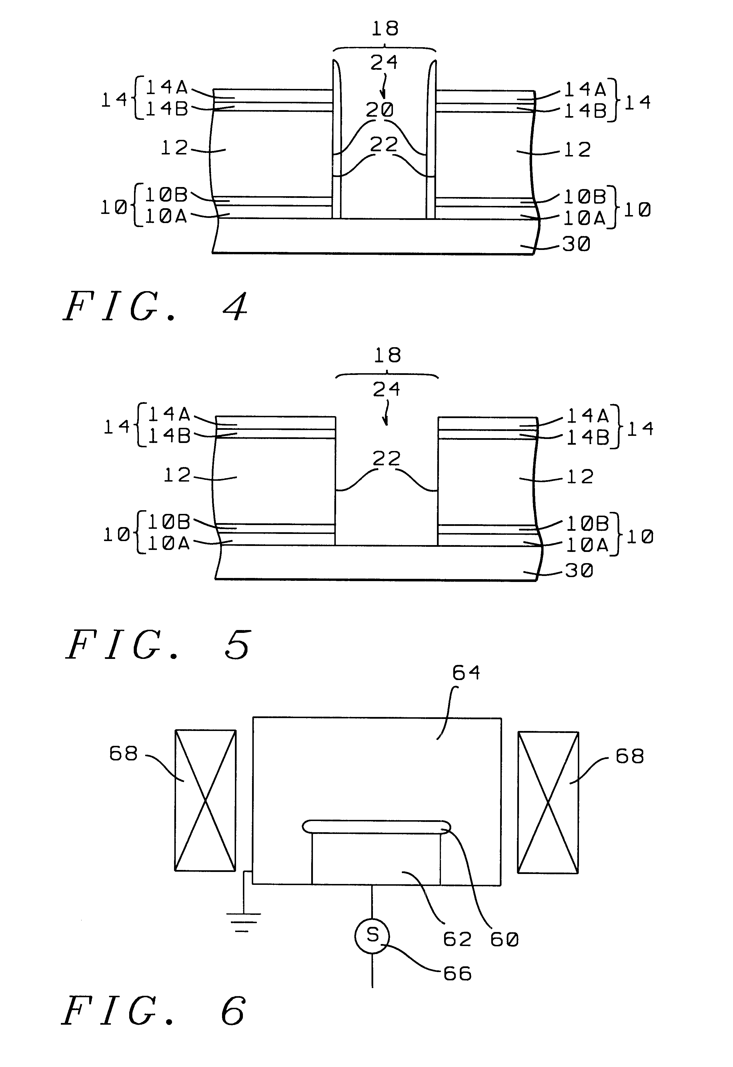
STEP I. low pressure of less than 50 millitorr, more preferably from about 10 to 50 millitorr, and most preferably about 20 millitorr;

medium RF power of greater than about 200 W, more preferably from about 200 to 500 W, and most preferably about 300 W;

a magnetic field greater than about 10 gauss (G), more preferably from about 20 to 100 gauss, and most preferably about 20 gauss at a radio frequency of about 13.56 MHz;

and the use of a fluorine containing gas / oxygen containing gas mixture having a preferable fluorine gas:oxygen gas ratio about 1 to 4; the fluorine containing gas may be CF.sub.4, NF.sub.3, or CHF.sub.3, and is preferably CF.sub.4 ; the oxygen containing gas may be O.sub.2, or O.sub.3, and is preferably O.sub.2.

at a hardware setting temperature from about 20 to 100.degree. C.;

for from about 10 to 60 seconds and more preferably from about 28 to 32 ...


PUM

PropertyMeasurementUnit
Timeaaaaaaaaaa
Timeaaaaaaaaaa
Timeaaaaaaaaaa

Abstract

A dry cleaning method for use in semiconductor fabrication, including the following steps. An etched metallization structure is provided and placed in a processing chamber. The etched metallization structure is cleaned by introducing a fluorine containing gas/oxygen containing gas mixture into the processing chamber proximate the etched metallization structure without the use of a downstream microwave while applying a magnetic field proximate the etched metallization structure and maintaining a pressure of less than about 50 millitorr within the processing chamber for a predetermined time.

Description

The present invention relates generally to methods of forming metal structures in semiconductor devices and specifically to methods of using a dry cleaning method instead of a traditional wet clean method after metal etch.Prevention of metal corrosion and pitting defects with conventional wet cleaning methods after metal etching is difficult. Wet cleaning methods can leave chlorine (Cl.sub.2) trapped in a thin sidewall polymer which maximizes corrosion and pitting of, for example, an aluminum (Al) or aluminum alloy substrate. If a thicker sidewall polymer is formed to minimize the exposure of the aluminum / aluminum alloy substrate to Cl.sub.2, the difficulty of a more narrow window within which to perform the wet clean arises.Therefore, passivation (formation of the sidewall polymer within the etched structure) during dry etching and clean step is a critical step. Sometimes an adequate passivation step followed by a poor clean step will also cause pitting and corrosion. With device d...

Claims


Application Information

Patent Timeline
IPC IPC(8): H01L21/02H01L21/3213
CPCH01L21/02071Y10S438/906Y10S134/902H01L21/32136
Inventor CHANG, HONG-LONGKUNG, MING-LILU, HUNGYUEHLIU, FANG-FEI
Owner PROMOS TECH INC
Why Eureka
Try Eureka