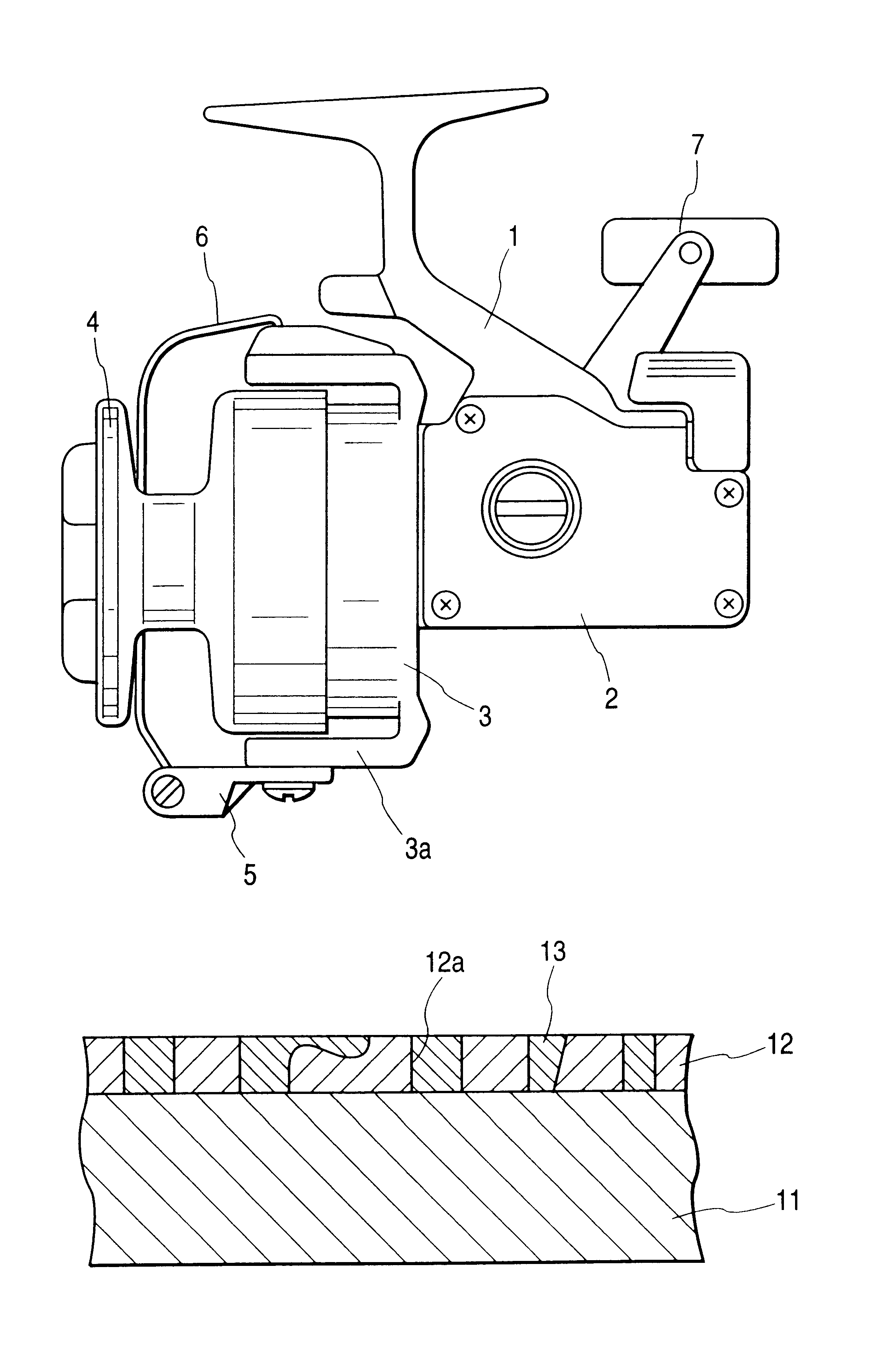
Eureka AIR delivers breakthrough ideas for toughest innovation challenges, trusted by R&D personnel around the world.

Component member of fishing reel

a technology of component parts and reels, which is applied in fishing, machines/engines, reels, etc., can solve the problems of inability to obtain accurate component parts for reels, inability to achieve high-precision dimensions of surface coating layers, and inability to achieve high-precision dimensions

Inactive Publication Date: 2003-03-18
DAIWA SEIKO CORPORATION
View PDF1 Cites 10 Cited by
  • Summary
  • Abstract
  • Description
  • Claims
  • Application Information

AI Technical Summary

Benefits of technology

The inventors of the invention has focused attention on the characteristics of a magnesium material. That is, the magnesium material exhibits high strength, very light weight and satisfactory moldability. Moreover, the surface of the magnesium material is subjected to a high-voltage anodization process to form a corrosion prevented layer or a sealing layer on the corrosion prevented layer formed by the anodization process. Thus, a fact has been detected that satisfactory corrosion resistance can be realized even in a severe environment in which sea-water and water easily adhere and the fishing gear is easily damaged owing to a rock or the like. Hence it follows that the present invention has been achieved.

Problems solved by technology

Since the fishing reel is distinct from products for other technical fields, and the fishing reel is used in a very severe environment in which sea-water and water adhere to the fishing reel.
However, the dimensions of the surface coating layer cannot easily be realized with high accuracy such that dispersion of the dimension is prevented.
If the Mg alloy is employed by focusing attention on the characteristics that the Mg alloy is a strong and light-weight material, an accurate component member for a reel cannot be obtained.
In the foregoing case, it is difficult to control the dimensions of the coating on the surface of the component member in high accuracy.
Moreover, the coating process becomes too complicated.
Thus, a fact has been detected that satisfactory corrosion resistance can be realized even in a severe environment in which sea-water and water easily adhere and the fishing gear is easily damaged owing to a rock or the like.
Moreover, contact corrosion does not easily occur.
If the thickness is smaller than 5 .mu.m, the hardness of the coating film is unsatisfactory.
If the thickness is larger than 20 .mu.m, there is apprehension that a crack occurs during growth of the coating film.

Method used


Image

  • Component member of fishing reel
  • Component member of fishing reel
  • Component member of fishing reel

Examples


example 2

This example has a structure similar to that according to Example 1 except for a structure that the corrosion prevented layer is formed by a high-voltage anodization process and the sealing layer is formed by impregnation with acrylic resin.

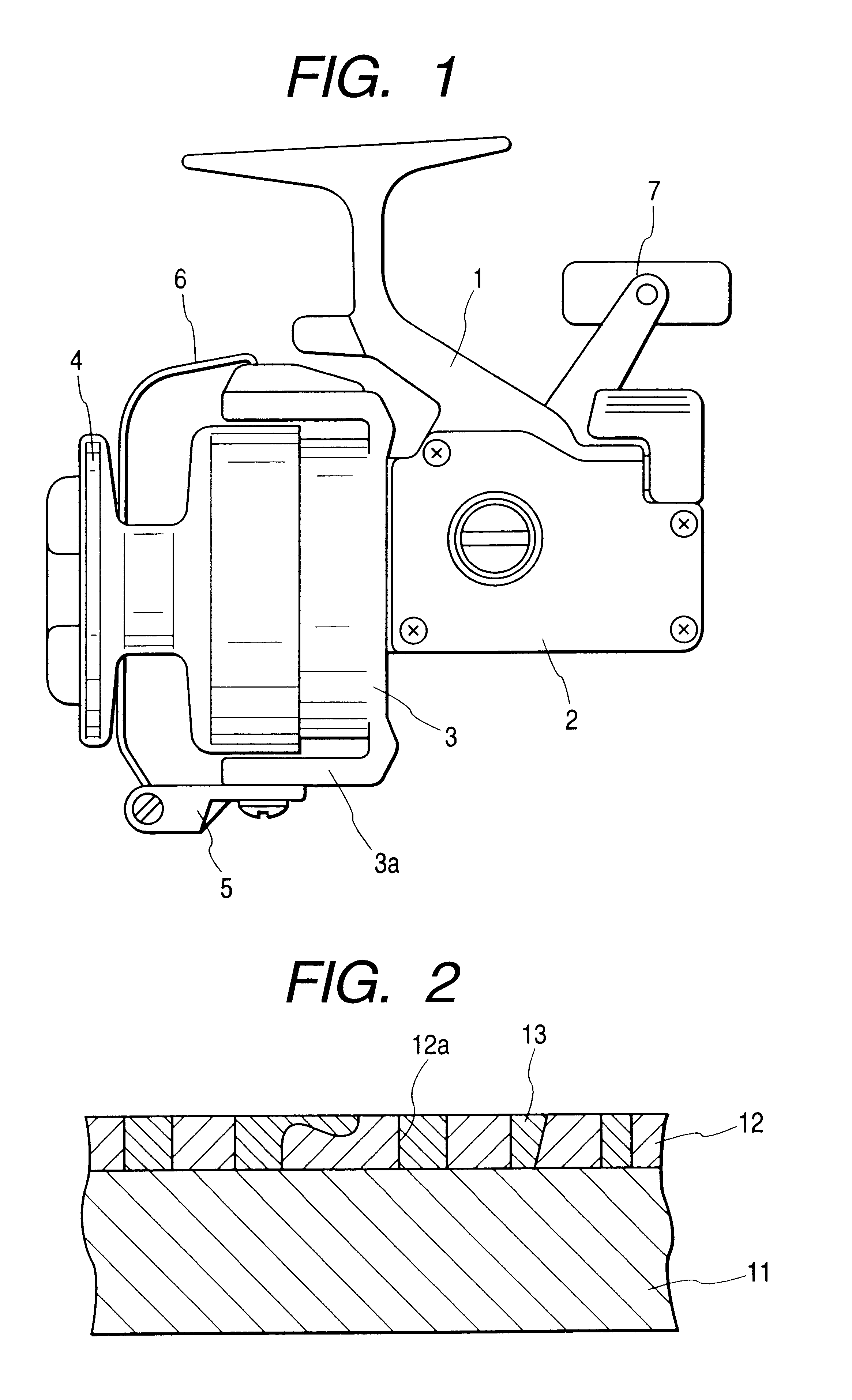
The corrosion prevented layer 12 is formed by: introducing the body 11, removed the point of contact, into processing solution adjusted by using organic electrolytic solution; and subjecting the body 11 to a high-voltage anodization process under a condition that an electric current is passed for a predetermined time. The sealing layer 13 is formed by an impregnation process using acrylic resin. The sealing layer 13 is formed such that the inside portion of openings 12a and recesses in the converted film, which constitutes the corrosion prevented layer 12, are filled with silica. Since the sealing layer 13 is formed by the impregnation process, change in the dimensions can be prevented.

The weight of the component member (the reel body) for the fi...

example 3

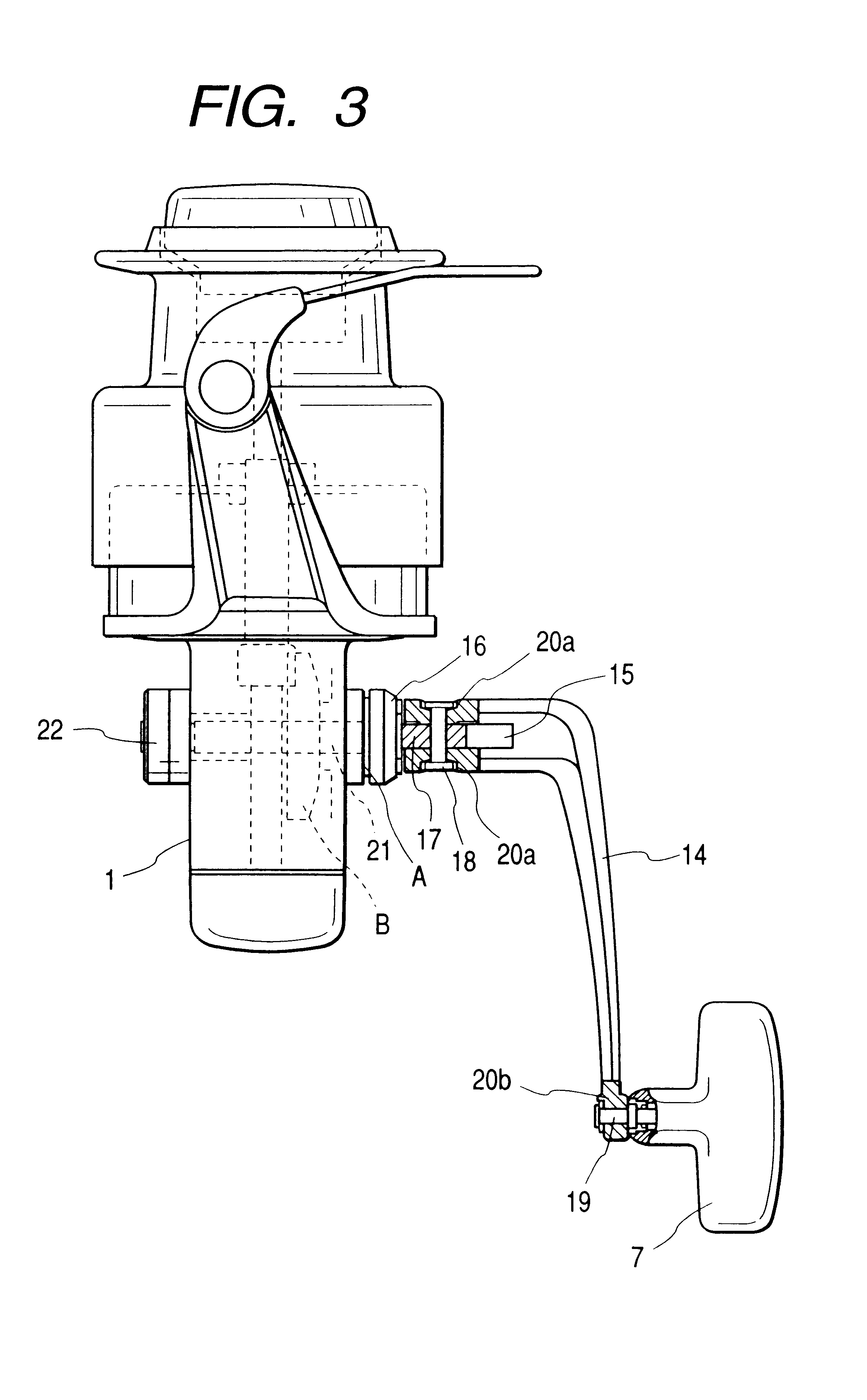
FIG. 3 is a schematic view showing a case in which the component member of a fishing reel according to the present invention is a handle of a spinning reel. In FIG. 3, reference numeral 21 represents a shaft which penetrates the reel body 1 so as to be connected to a reel operating member B disposed in the reel body 1. A handle stand 17 is joined to either end of the shaft 21. A cap 22 for preventing exposure of the shaft 21 is joined to another end of the shaft 21. A cap 16 is joined between the shaft 21 and the handle stand 17 at a position opposite to the cap 22.

A handle arm 14 is joined to the handle stand 17 through a handle stopper 15. Specifically, the handle stand 17 and the handle arm 14 are connected by riveting a handle-stand rivet 18 such that folding is permitted. As is known, the handle arm 14 is permitted in a winding state and a accommodating state and is permitted to move ups and down due to operating the handle stopper 15. A handle knob 7 is joined to the distal en...

example 4

Referring to FIG. 8, a method of forming an organic coating layer 30 on a corrosion prevented layer 28 will now be described.

The organic coating layer 30 is formed by a dry coating method (a CVD method, a sputtering method, a vacuum evaporation method, an ion plating method or the like).

The foregoing CVD method is performed such that an organic material is produced in a gas phase. Thus, a film (the organic coating layer 30) is formed. The sputtering method is performed such that an organic material is sputtered. Thus, a film (the organic coating layer 30) is formed. The vacuum evaporation method and the ion plating method are performed such that an organic material is evaporated. Thus, the film (the organic coating layer 30) is formed. As the thickness of the formed film is enlarged, administration of the film becomes difficult and the smoothness of the surface of the film deteriorates. Therefore, it is preferable that the thickness of the organic coating layer 30 is 1 .mu.m to 20 ....


PUM

PropertyMeasurementUnit
thicknessaaaaaaaaaa
thicknessaaaaaaaaaa
thicknessaaaaaaaaaa

Abstract

A component member of a fishing reel incorporating a body constituted by a Mg alloy; and a corrosion prevented layer formed on the body by a high-voltage anodization process or a body constituted by a Mg alloy; a corrosion prevented layer formed on the body by a high-voltage anodization process or conversion treatment; and a sealing layer which is formed on the corrosion prevented layer by an impregnating process and which is free from any change in the dimension thereof.

Description

1. Field of the InventionThe present invention relates to a component member of a body (the body, the cover, the rotor and the frame) and the handle of a spinning reel for fishing.2. Related ArtHitherto, use of a magnesium material to constitute the member of a fishing reel has been investigated and embodied from viewpoints of increasing the strength, reducing the weight and facilitating molding.Since the fishing reel is distinct from products for other technical fields, and the fishing reel is used in a very severe environment in which sea-water and water adhere to the fishing reel. Therefore, satisfactory contrivances must be employed.In consideration of the foregoing circumstance, a method has been disclosed in JP-A-9-168352. In this disclosure, the component member of the fishing reel formed by a magnesium alloy is anodized to form a corrosion prevented layer. Then, resin coating, such as electrodeposition or spray coating, is performed to obtain required corrosion resistance an...

Claims


Application Information

Patent Timeline
Patent Type & Authority Patents(United States)
IPC IPC(8): A01K89/00A01K89/01A01K1/00
CPCA01K89/01Y10S242/90A01K89/01121C25D11/30
Inventor KOIKE, MAMORU
Owner DAIWA SEIKO CORPORATION
Why Eureka
Eureka Blog
Learn More