High-pressure mercury lamp

a high-pressure mercury and discharge lamp technology, which is applied in the direction of discharge tube luminescnet screens, identification means, instruments, etc., can solve the problems of long time for light flux to reach 90% of its stable state, and long light buildup time, so as to improve the life of the lamp and reduce the light buildup time. , the effect of excellent luminous efficiency

Inactive Publication Date: 2003-03-25
PANASONIC CORP
View PDF17 Cites 16 Cited by
  • Summary
  • Abstract
  • Description
  • Claims
  • Application Information

AI Technical Summary

Benefits of technology

With this construction, the second light emitting material with a shorter light buildup time emits light immediately after the lamp is started up, and the first light emitting material gradually emits light. Here, as the first light emitting material, it is preferred to use a material having an excellent luminous efficiency and an advantage contributing to an increase in t

Problems solved by technology

Using this conventional high-pressure mercury lamp, however, there has been a problem that it takes a long time for light flux to attain 90% of its stable state after the lamp is started up (this period of time is referred to as the "light buildup time" hereinafter).
This unavoidably leads to a longer light buildup time.
Although the conventional high-pressure mercury lamp provides high intensity, it has a problem about

Method used


Image

  • High-pressure mercury lamp
  • High-pressure mercury lamp
  • High-pressure mercury lamp

Examples


first embodiment

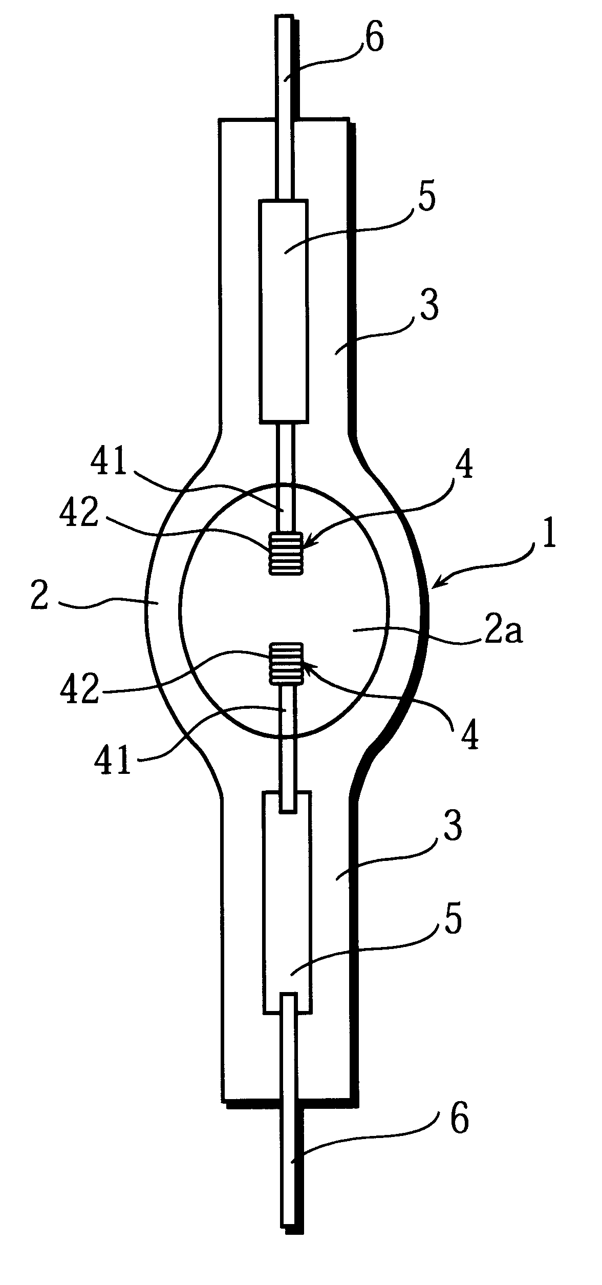
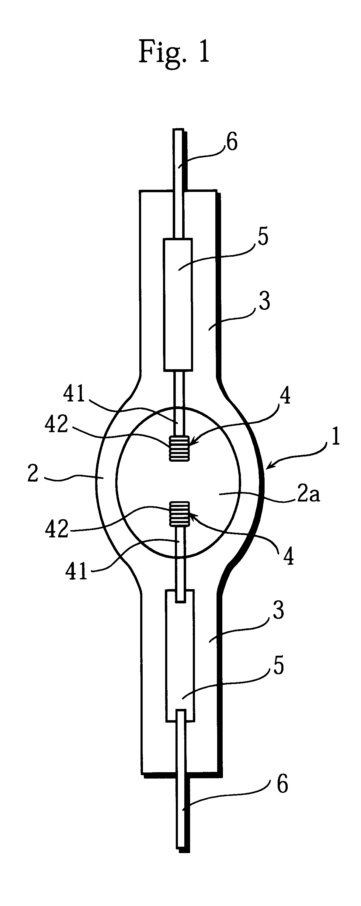
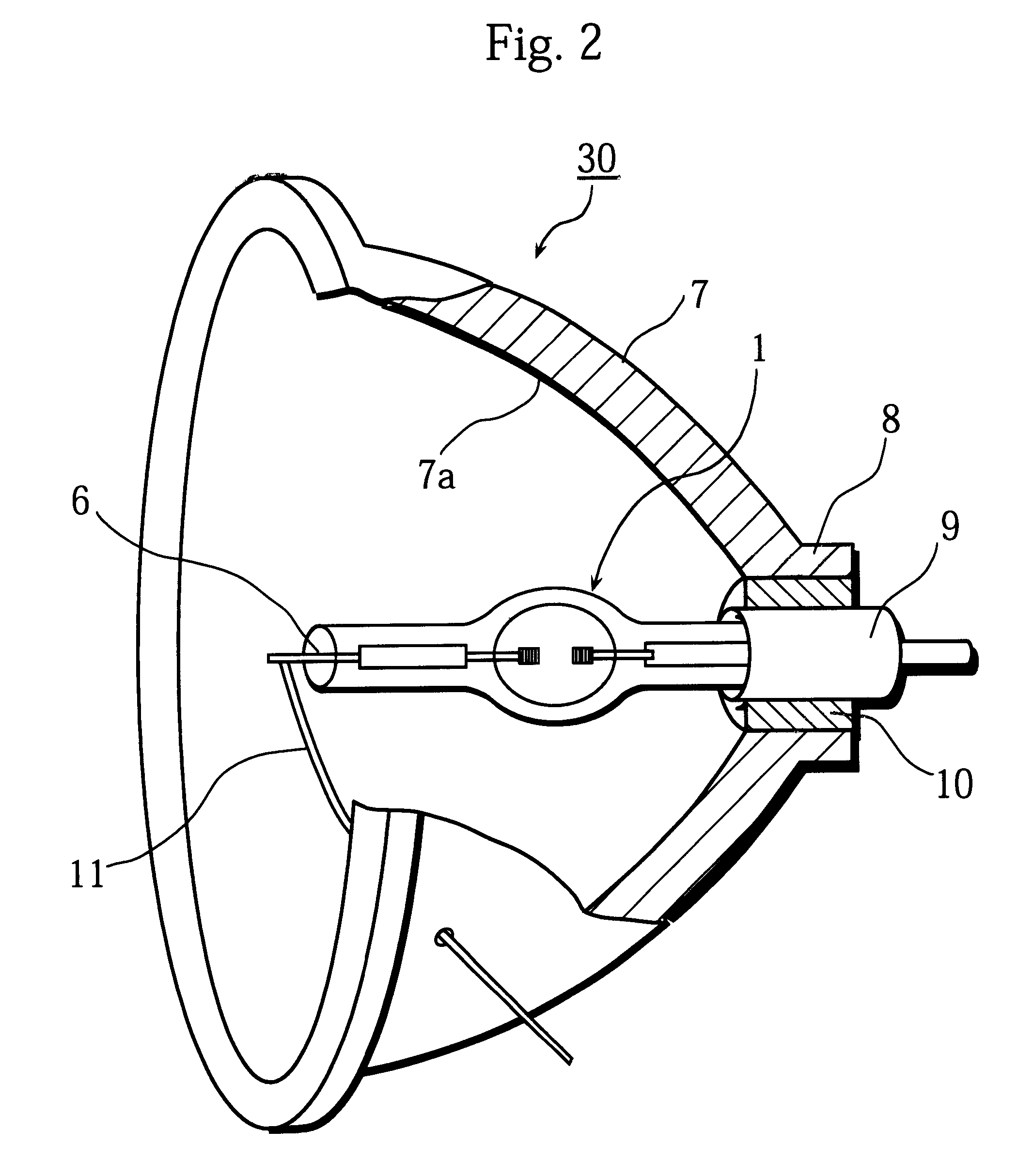
FIG. 1 is a front view of a high-pressure mercury lamp 1 of the first embodiment of the present invention. As shown in this figure, the high-pressure mercury lamp 1 is composed of a tube 2 with a pair of sealing parts 3, a pair of electrodes 4, and so on. The tube 2 is made of quartz glass, with its middle part in the direction of the length being spheroid. The maximum internal diameter of the central part of the tube 2 is 7.0 mm, the capacity of the tube 2 is 240 mm.sup.3, and the wall thickness is 2.5 mm. A sealing part 3 is provided at both ends of the tube 2.

In a discharge space 2a of the tube 2, 36 mg of mercury (about 0.16 mg / mm.sup.3), 9.0.times.10.sup.-5 .mu.mol / mm.sup.3 of bromine (Br) as a halogen substance, and an appropriate amount of xenon gas (which will be described later) are sealed.

A pair of electrodes 4 is provided in the discharge space 2 a of the tube 2. Each electrode 4 has an electrode rod 41 and an electrode coil 42 provided at the tip of the electrode rod 41,...

second embodiment

The following is a description of a high-pressure mercury lamp 60 of the second embodiment.

FIG. 5 is a front view of the high-pressure mercury lamp 60. The high-pressure mercury lamp 60 is a direct-current (DC) type lamp. As shown in FIG. 5, a cathode 18 and an anode 21 are provided in a discharge space 2a. The cathode 18 includes an electrode coil 17 and an electrode rod 16, the electrode coil 17 being wound around the end of the electrode rod 16 leaving 0.75 mm at the tip of the rod 16 uncovered. The anode 21 includes an electrode tip 20 and an electrode embedding rod 19, the electrode tip 20 being set on the tip of the electrode embedding rod 19. The electrode embedding rod 19 is 0.4 mm in the outer diameter. The electrode tip 20 is made of tungsten whose content of potassium oxide is 5 ppm or less, and is 1.8 mm in the maximum outer diameter and 0.7 mm in the tip-end diameter. The high-pressure mercury lamp 60 is lit up through the application of a DC voltage between the cathode...


PUM


Abstract

A high-pressure mercury lamp includes an arc tube, and a pair of electrodes is provided in a discharge space of the arc tube. In the discharge space, mercury and xenon gas are sealed. The amount of mercury per unit volume that is to be sealed in the discharge space is within a range of 0.12 mg/mm3 to 0.35 mg/mm3. A pressure of the xenon gas in the discharge space is within a range of 2.0x10⁵ Pa to 2.0x10⁶ Pa.

Description

(1) Field of the InventionThe present invention relates to a high-intensity discharge lamp and high-pressure mercury lamp that are used in general lighting fixtures and optical instruments, and also relates to an illumination device using the high-pressure mercury lamp and an image display apparatus using the illumination device.(2) Description of Prior ArtConventionally, in an illumination device used in an image display apparatus such as a liquid crystal projector, a light source and a concave reflecting mirror are usually formed in one piece. As the light source, a high-pressure mercury lamp with a short arc, which is close to a point light source, has been used. The high-pressure mercury lamp has advantages, such as an excellent luminous efficiency, high intensity, favorable balance of red, blue, and green in emitted light, and long lifetime.Such a high-pressure mercury lamp is provided with a glass tube with sealing parts set at its both ends, the glass tube including a pair of...

Claims


Application Information

Patent Timeline
IPC IPC(8): H01J61/00H01J61/12H01J61/20H01J61/82H01J61/073G03B21/14G09F9/00H01J61/30H01J61/88
CPCH01J61/822H01J61/20
Inventor TAKEUCHI, NOBUYOSHI
Owner PANASONIC CORP
Why Eureka
Try Eureka