Device for monitoring temperature distribution on the basis of distributed fiber-optic sensing, and use of same

a technology of distributed fiber optics and sensors, applied in the direction of heat measurement, optical radiation measurement, instruments, etc., can solve the problems of scattered light and signal processing with higher linearity requirements, laborious, and high cost of pressure measuremen

Inactive Publication Date: 2003-04-15
O FUR SENSORIK GEOTECHNN UMWELTSCHUTZ & MATHEMATISCHE MODELLIERUNG MBH JENA
View PDF18 Cites 54 Cited by
  • Summary
  • Abstract
  • Description
  • Claims
  • Application Information

AI Technical Summary

Problems solved by technology

In contrast thereto, however, the more problematical measurement of the scattered light and a signal processing with higher linearity requirements, which is more laborious due to the Fourier transformation, have to be taken into account.
Furthermore, the costs for such pressure measurements are considerable.
The detection of a temperature development in terms of time is not possible or only with problems.
Given a large building excavation this results in high pumping times, wherein the disadvantage of the cited known solution moreover consists in that monitoring of the vertical wall is not possible or only realizable with restricted quality.
Leakages result in local temperature anomalies, which develop within a short time, i.e. within a few minutes up to hours.
As large quantities of data have to be processed by taking into account reference values in each case, and as it is necessary to constantly remove natural temperature variations from the current measuring values, known evaluation methods require a lot of time and / or calculations, so that an online evaluation is partially not possible or only with restrictions.
In view of the time dynamics of the measurements it must be noted that the used fiber-optic sensor cable results in a short delay of the temperature measurement due to its construction, which can last up to several minutes in dependence on the thermal contact with the ambient medium.
This results in clear temperature differences between the ground water outside the excavation and the water inside the excavation.

Method used


Image

  • Device for monitoring temperature distribution on the basis of distributed fiber-optic sensing, and use of same
  • Device for monitoring temperature distribution on the basis of distributed fiber-optic sensing, and use of same
  • Device for monitoring temperature distribution on the basis of distributed fiber-optic sensing, and use of same

Examples


Embodiment Construction

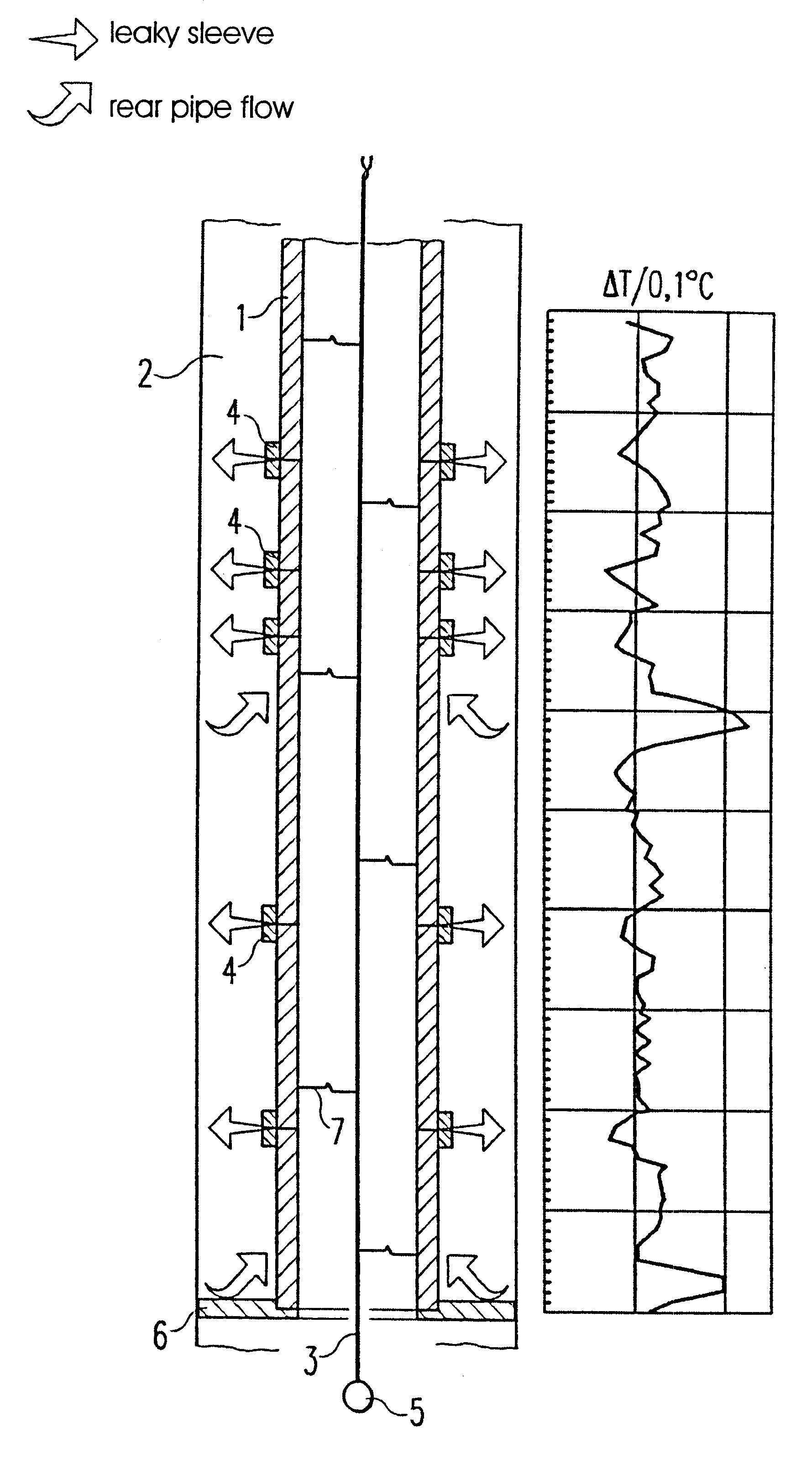
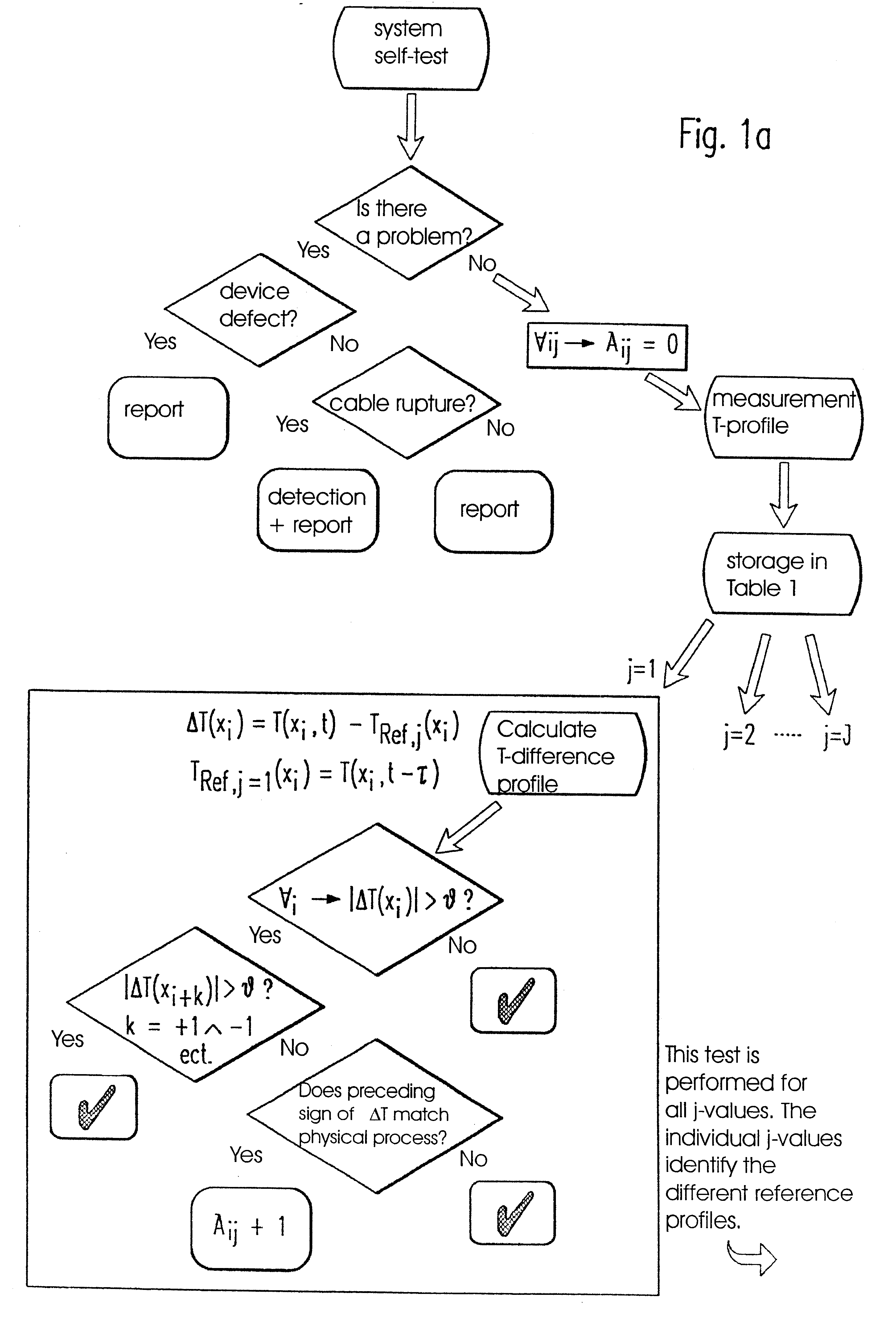
In the embodiment shown in the FIGS. 1a and 1b, at first a preferably provided self-test of a fiber-optic temperature measuring device is assumed. The actual measurement and evaluation of the current temperature profiles takes place after the device has signaled readiness for operation.

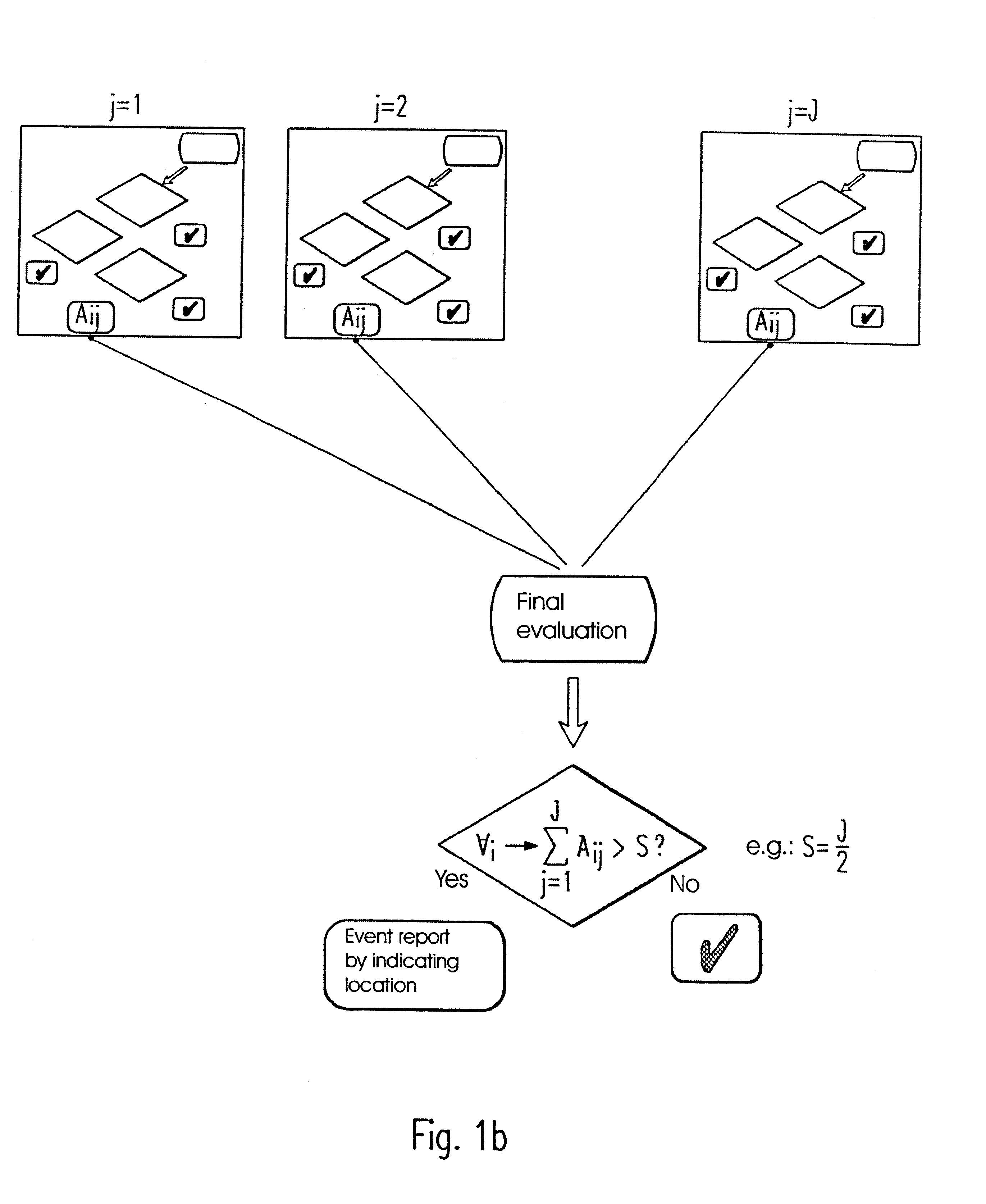
According to the embodiment local extremes, i.e. minimums and maximums, are recognized without numeric derivations. Problems are thereby surpassed, which can otherwise occur during numeric differentiation of temperature profiles due to signal noise or the spacial and temporal temperature variations being characteristic for the respective pipeline. The reference profiles T.sub.Ref,j required for evaluating the current measuring results are specified and provided with corresponding indices. The selected preadjustments are freely programmable in order to allow for individual adjustments of the monitoring system to the respective measuring task.

An exemplary selection for the time margin between two temper...


PUM

PropertyMeasurementUnit
lengthaaaaaaaaaa
lengthaaaaaaaaaa
temperatureaaaaaaaaaa

Abstract

The invention relates to a method and a device for monitoring, also permanently and automatically, temperature distributions and/or temperature anomalies on the basis of distributed fiber-optic temperature sensing as well as to the use of such methods. According to the invention the detection of local temperature extremes, i.e. minimums or maximums, in view of the evaluation is performed by an evaluation without numeric derivations. With the device for monitoring ascending and supply pipes surrounded by an annular space it is possible to check the safety of pressurized installations, particularly in the field of low-pressure gas storage, in a cost-efficient manner. Moreover, the position of an underground watershed or respectively the direction and flow rate of the flows in flooded drift sections can be determined on the basis of fiber-optic temperature measurements. The defined arrangement of preferably vertical sensor cables inserted into the bores also makes it possible to examine the tightness of base sole and lateral walls in building excavations. Finally, the virtually horizontal, meander-shaped arrangement of fiber-optic cables situated in several levels makes it possible to evaluate and control the efficacy and homogeneity of leaching processes in leaching dumps and fills.

Description

1. Field of the InventionThe invention relates to a method and a device for monitoring temperature distributions and / or temperature anomalies on the basis of distributed fiber-optic temperature sensing as well as to novel applications of such methods.2. Description of the Related ArtDistributed fiber-optic measurement principles use the integration of laser light impulses into an optical waveguide and the scattering effects thereof. The scattering of the laser light impulse takes place on the molecules of the optical waveguide. A small part of the laser light is thereby scattered back. The intensity and the spectral composition of the scattered light is accordingly determined by the molecules in the optical waveguide and by the behavior of the molecules.The backscattered light is composed of different spectral portions, which are caused by different mechanisms of the interaction between laser light and the optical waveguide components and which thereby also include different informa...

Claims


Application Information

Patent Timeline
Patent Type & Authority Patents(United States)
IPC IPC(8): G01M3/00F17D5/00F17D5/06G01M3/02G01K11/12
CPCG01M3/002F17D5/06
Inventor GROSSWIG, STEPHANKUHN, KATRIN
Owner O FUR SENSORIK GEOTECHNN UMWELTSCHUTZ & MATHEMATISCHE MODELLIERUNG MBH JENA
Why Eureka
Try Eureka