Decoupling sleeve for mounting in a motor vehicle exhaust pipe
a technology for exhaust pipes and decoupling sleeves, which is applied in the direction of mechanical equipment, machines/engines, adjustable joints, etc., can solve the problems of no tension, no twisting, no deformation in bending, shear, or compression, and no stiff sleeves
- Summary
- Abstract
- Description
- Claims
- Application Information
AI Technical Summary
Benefits of technology
Problems solved by technology
Method used
Image

Examples
first embodiment
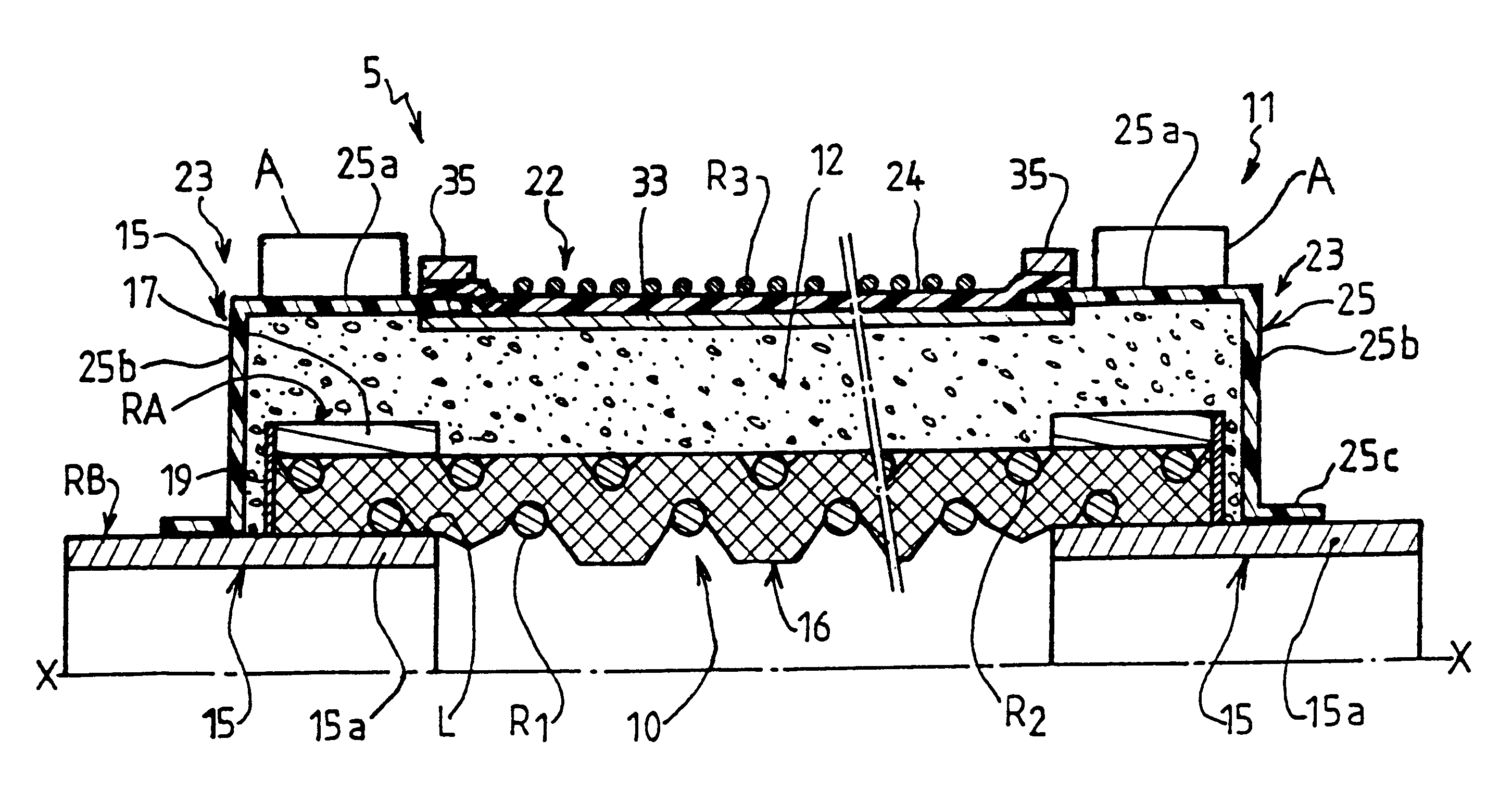
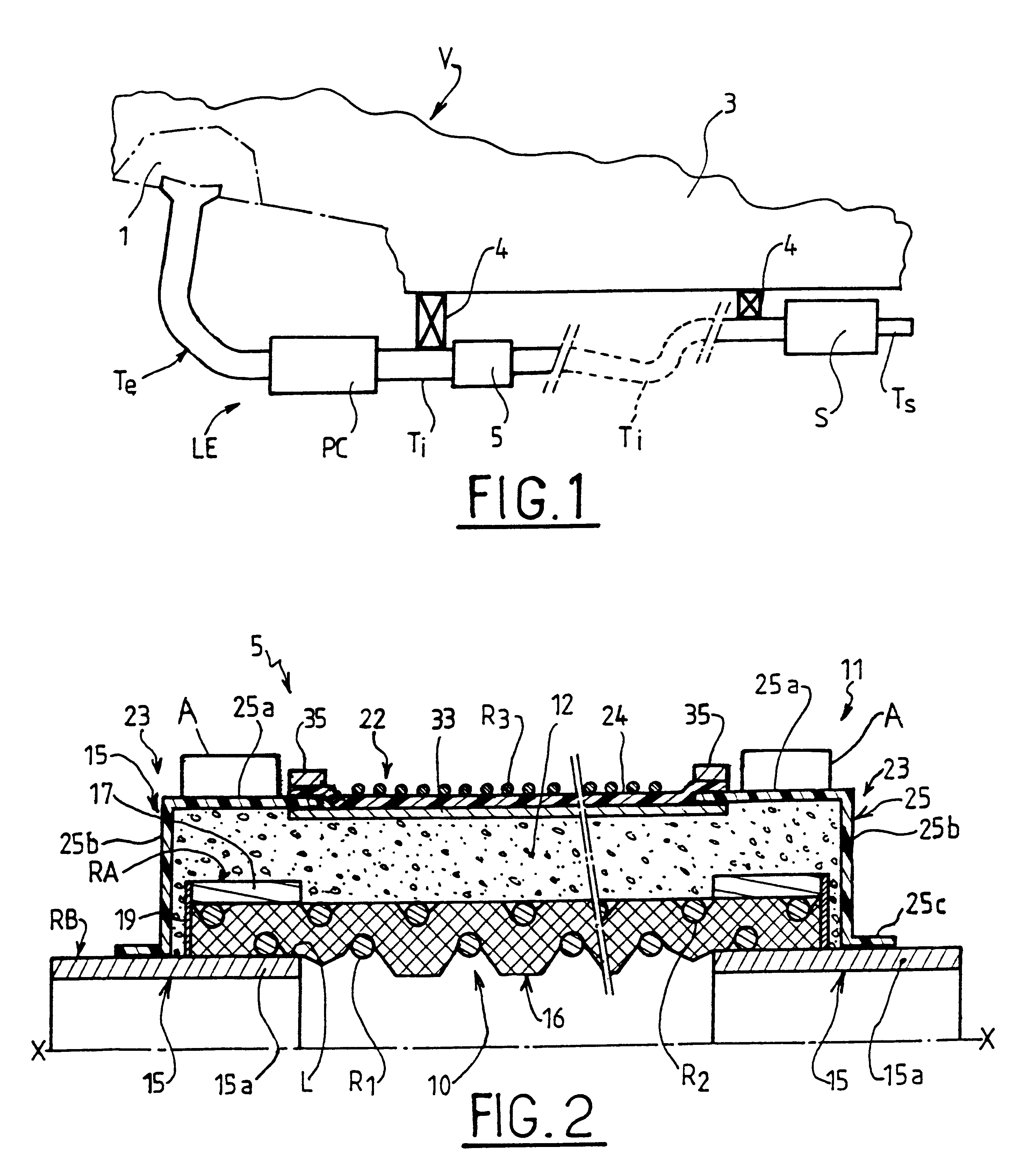
In a first embodiment as shown in FIG. 2, the mechanical portion 10 comprises, in the axial direction, two rigid and continuous end zones 15 in the form of two metal tubular coupling endpieces 15a, e.g. made of stainless steel, which endpieces are connected to each other by a flexible mechanical link 16 capable of accommodating angular deflections.
The flexible link 16 of the mechanical portion 10 forms an inner cylindrical covering which comes into contact with exhaust gases and which is made of a material which must be mechanically strong which must withstand high temperatures. In this first embodiment, the flexible link 16 is made of stainless steel wires or fibers in the form of a fabric, a braid, a knit, . . . , it being understood that it is preferable to use an oriented structure of long fibers that hold on to one another. By way of example, a woven fabric of stainless steel fibers oriented at 45.degree. and forming a pad that is thin, dense, and strong can be suitable.
Advanta...
second embodiment
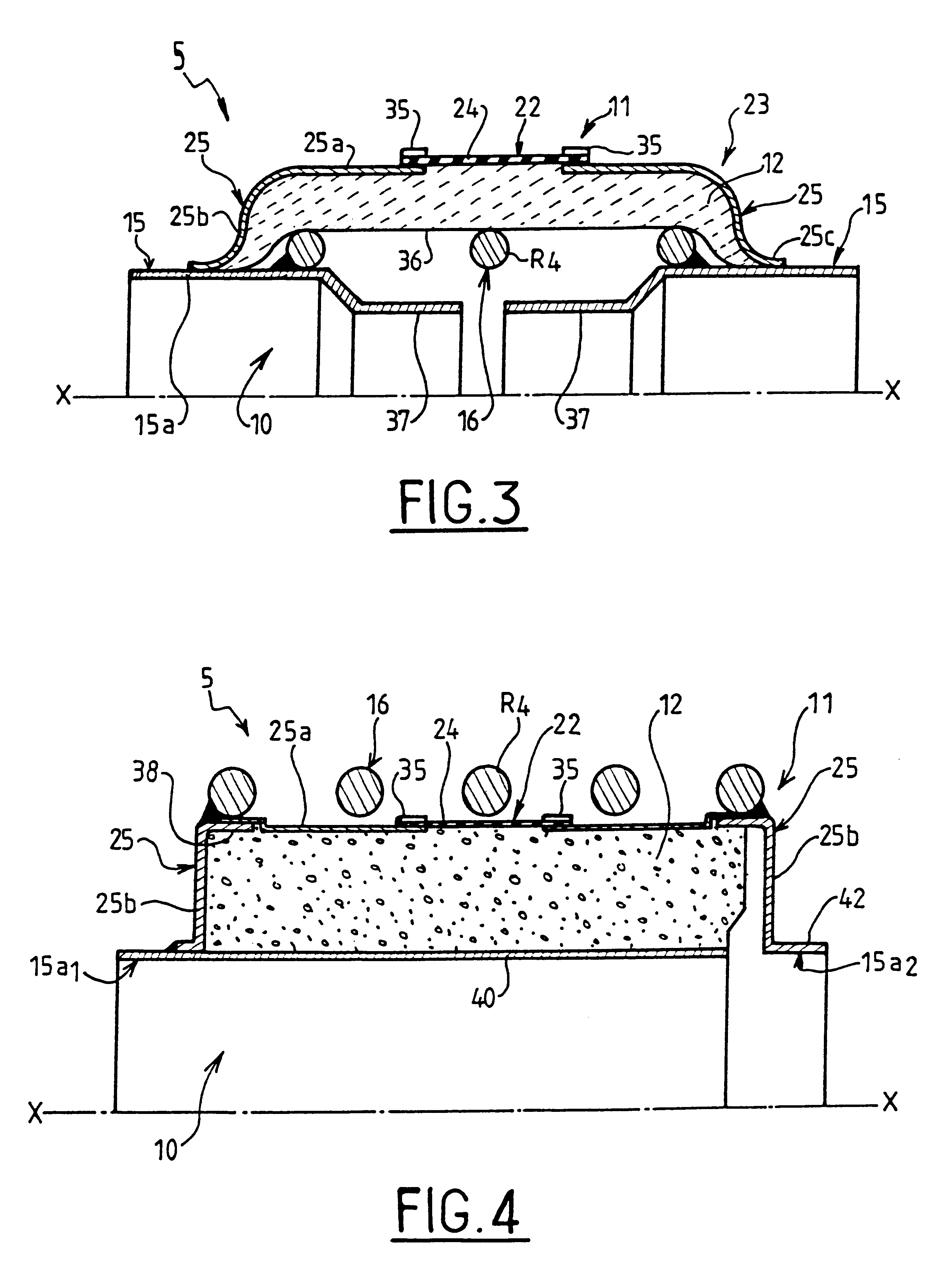
In a second embodiment shown in FIG. 3, the flexible link 16 which interconnects the two connection endpieces 15a of the mechanical portion 10 of the sleeve is constituted by a spring R4 of metal wire which is about 5 mm to 14 mm thick, and which serves essentially to contribute to transmitting any forces.
The sealing portion 11 of the sleeve 5 then also comprises an inner covering 36 in the form of a thin foil of stainless steel which is interposed between the spring R4 and the thermal insulation portion 12.
Each connection endpiece 15a can be a simple tubular element to which the respective ends of the spring R4 are welded so as to provide mechanical continuity.
Advantageously, each connection endpiece 15a can be extended axially inside the sleeve by a respective tubular element 37 that is in axial alignment therewith and that forms a deflector.
In a variant, the deflector can be constituted by a single tubular element extending that one of the connection endpieces 15a that is located...
third embodiment
In a third embodiment as shown in FIG. 4, the flexible link 16 of the mechanical portion 10 of the sleeve 5 is likewise constituted by a spring R4 of the same type as that shown in FIG. 3, but which is mounted on the outside of the sealing portion 11 so as to surround both it and the insulation portion 12 associated therewith.
The axial and transverse portions 25a and 25b of each cover 25 can form two elements that are fixed to each other by welding, the transverse portion 25b being thicker than the axial portion 25a. Each end of the spring R4 is welded to a rim 38 of the transverse portion 25b of each cover 25.
The sealing portion 11 further comprises a thin inner covering 40 of stainless steel which comes into contact with the exhaust gases. This covering 40 is thus surrounded by the insulation portion 12. One axial end of the covering 40 is welded to a rigid connection endpiece 15a, of the mechanical portion 10 or can be integral with said endpiece 15a.sub.1 while being of smaller ...
PUM
 Abstract
Description
Claims
Application Information
 - Generate Ideas
- Intellectual Property
- Life Sciences
- Materials
- Tech Scout
- Unparalleled Data Quality
- Higher Quality Content
- 60% Fewer Hallucinations
Browse by: Latest US Patents, China's latest patents, Technical Efficacy Thesaurus, Application Domain, Technology Topic, Popular Technical Reports.
© 2025 PatSnap. All rights reserved.Legal|Privacy policy|Modern Slavery Act Transparency Statement|Sitemap|About US| Contact US: help@patsnap.com