Carburetor throttle control detent mechanism

a technology of detent mechanism and carburetor, which is applied in the direction of heating type, separation process, application, etc., can solve the problems of low displacement, difficult if not economically impossible angular positioning, and detent of machine, and achieve the effect of reducing manufacturing and assembly costs and small and precise increments

Inactive Publication Date: 2003-05-13
WALBRO ENGINE MANAGEMENT
View PDF15 Cites 17 Cited by
  • Summary
  • Abstract
  • Description
  • Claims
  • Application Information

AI Technical Summary

Benefits of technology

Accordingly, among the objects of the present invention are to provide an improved carburetor throttle control detent mechanism that eliminates the need for the aforementioned ball and spring type detent mechanism and yet is also built into the carburetor assembly and hence does not require any cooperative construction either on the engine or the appliance on which the engine is installed, that achieves reduced costs of manufacture and assembly and yet is capable of controlling the throttle valve clocking operation in very small and precise increments, and that allows a choice of a plurality of predetermined positive detent stop positions for the throttle valve throughout the range of throttle valve operation from W.O.T. to fully closed.
In still another embodiment the first detent means on the carburetor comprises at least one pocket concavity formed in the body side surface and the second detent means comprises a lateral projection on the throttle lever detent arm oriented to ride on the body side surface and operably snap into the pocket concavity upon registry therewith by spring bias developed in the throttle lever detent arm. This embodiment provides the additional advantage of using the lateral projection as a replacement for the axially biasing spring typically found on current throttle controls.

Problems solved by technology

However in very small lawn and garden appliances, such as weed whips and leaf blowers, the engines are typically of small size and of low displacement, and therefore typically are provided with a cubic-type diaphragm carburetor that may only be between one and two inches square in outside dimensions.
Due to the minuscule dimensions of these detent mechanism parts involved in such tiny carburetors, and particularly the very small diametrical dimension of the throttle shaft, it is difficult in the first instance to machine the detent pockets on the throttle shaft, and even more difficult if not economically impossible to angularly locate the pockets to the sufficiently close manufacturing circumferential dimensional tolerances that would be required in order to accurately establish within close angular tolerances the predetermined positive position stops for the throttle valve at W.O.T., idle and closed valve settings.
In addition, there are the usual manufacturing and assembly costs involved in providing the spring and ball type throttle control detent mechanism, and these costs are particularly aggravated when producing very small cubic carburetors of the aforementioned type.

Method used


Image

  • Carburetor throttle control detent mechanism
  • Carburetor throttle control detent mechanism
  • Carburetor throttle control detent mechanism

Examples


first embodiment

of Carburetor Throttle Control Detent Mechanism

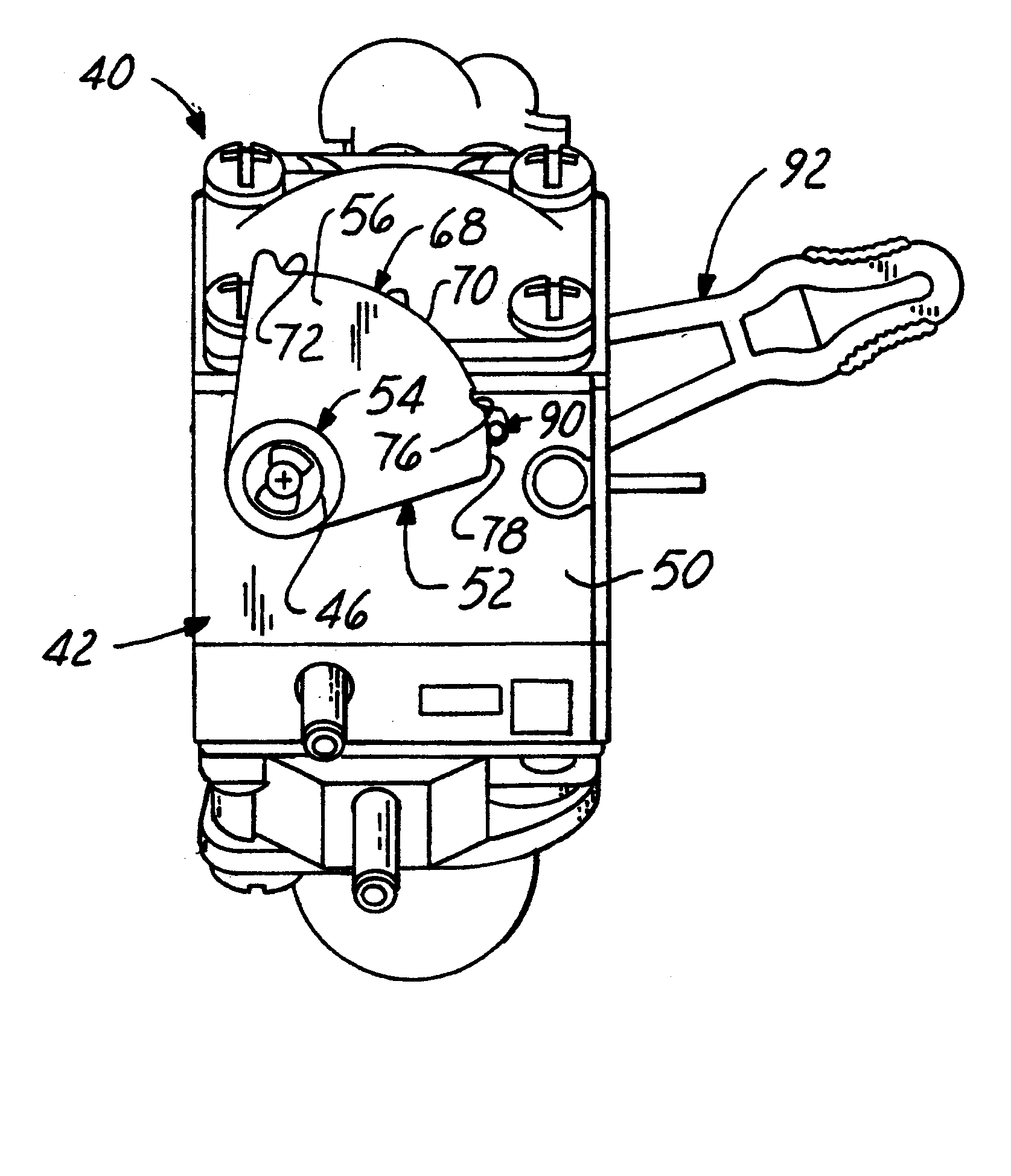
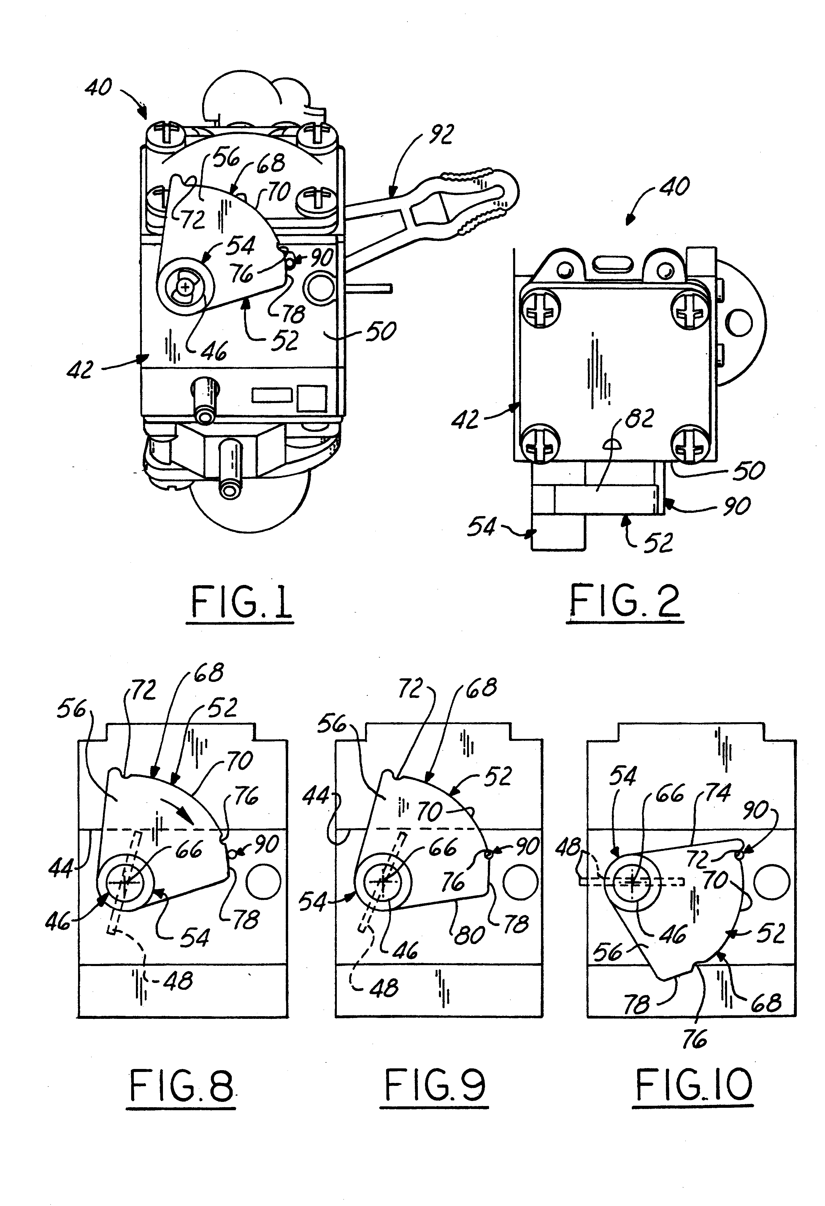
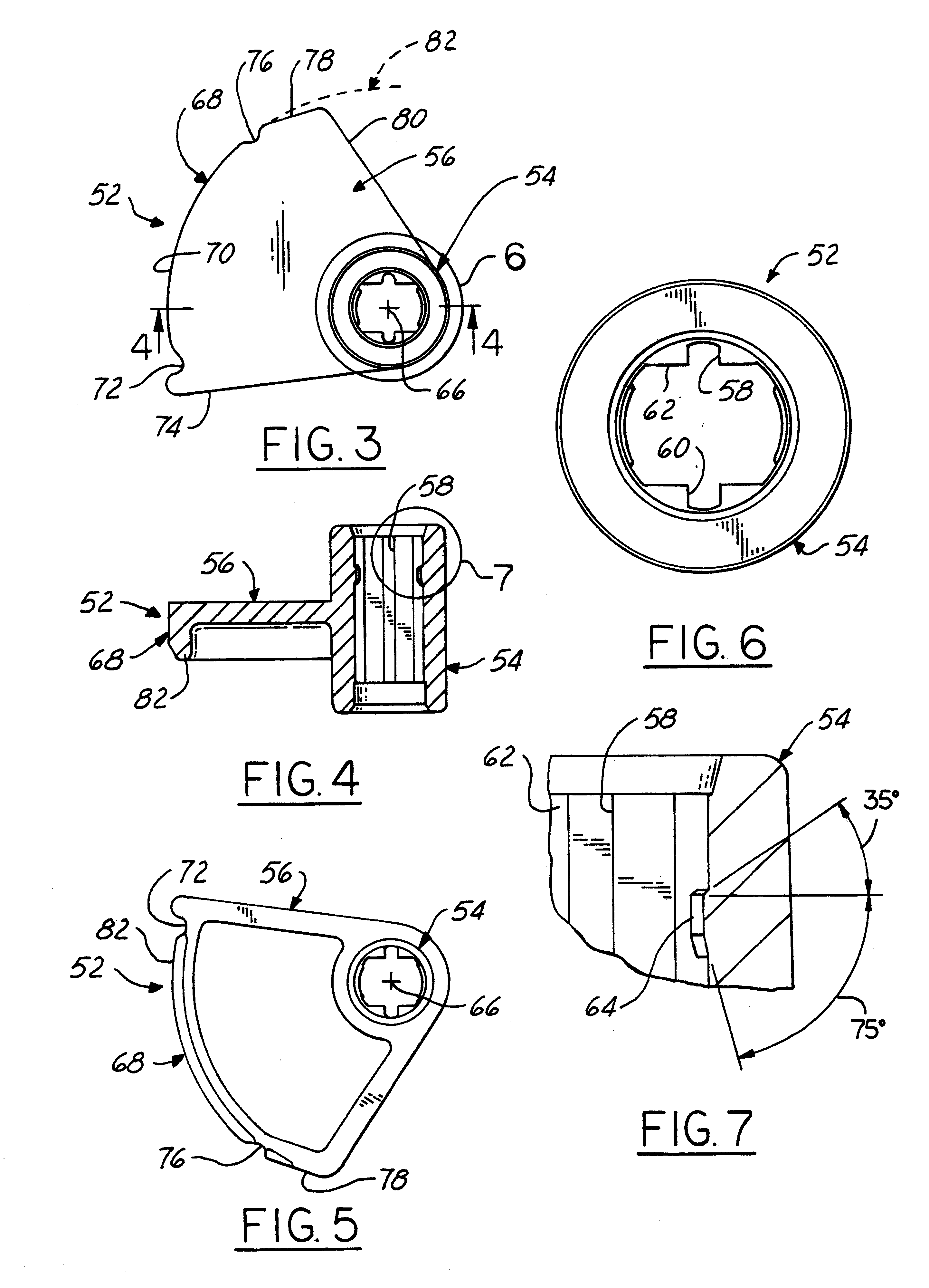
Referring in more detail to the accompanying drawings, FIGS. 1-10 illustrate a first embodiment carburetor throttle control detent mechanism of the invention as provided in conjunction with a conventional diaphragm type cubic carburetor 40 adapted for example, for use on a leaf blower appliance engine. Carburetor 40 has a generally cube-shaped body 42 that may typically measure only approximately one and a half inches (approximately 40 mm.) on each side. Body 42 has an air-fuel mixture through passageway 44 (FIGS. 8-10) and a cylindrical throttle valve shaft 46 journaled in body 42 for rotation about an axis 66 that extends across passageway 44 and carries a butterfly-type throttle valve blade 48 fixed thereon for rotation therewith. Due to the small size of carburetor 40, throttle shaft 46 necessarily has a given outside diameter of relatively small dimension, for example on the order of 3 / 16 inch (approximately 5 mm).

In accordance wit...

second embodiment

Carburetor Throttle Control Detent Mechanism

The second embodiment carburetor throttle control detent mechanism of the invention is illustrated in FIGS. 11-14 wherein elements alike in structure and / or function to those of the first embodiment are given a like reference numeral raised by a factor of 100. Carburetor 140 of the second embodiment is similar to carburetor 42 but is not of the "split" type. Rather the manually manipulated throttle lever 192 and the associated throttle lever detent arm 152 are both mounted on the same side of the carburetor, preferably using a mounting hub construction 154 similar to hub 54. Lever 192 and throttle lever detent arm 152 may be made as two separate components bonded together, or may be a one piece part made integral with one another by molding. ("Integral" as used herein means molded or cast as a one piece, unitary part). Throttle lever detent arm 152 differs from arm 52 only with respect to the formation of the detent for holding throttle va...

third embodiment

Carburetor Throttle Control Detent Mechanism

FIG. 15 illustrates a third embodiment of a throttle lever detent arm 252 of the invention. Detent arm 252 is identical to detent arm 52 except for having a large mass of material of the arm removed to leave a relatively wide arcuate slot 253 formed in blade 256 of the arm located radially between hub 254 and the peripheral edge cam control surface 268 of arm 252. Molding or machining arm 252 with slot 253 is advantageous in reducing the weight and material cost of the arm. Slot 253 also renders it possible to design-control radial deflection of the web portion 255 remaining between cam edge surface 268 and the arcuate radially outer edge 257 of slot 253. Slot 253 thus adds flexibility to the outer edge of arm 252 so that the same can provide spring stress for the detent mechanism, either alone or in combination with the spring stress provided by the material of pin 90. The contour of outer slot edge 257 thus may be varied to enhance the d...


PUM

PropertyMeasurementUnit
diameteraaaaaaaaaa
radiusaaaaaaaaaa
diameteraaaaaaaaaa

Abstract

A carburetor having a throttle valve co-rotatable with a small diameter throttle shaft having a free end protruding from an exterior side surface of the associated carburetor body. A throttle lever detent arm is co-rotatable on and with the throttle shaft free end adjacent each body surface. Interengageable detents on the detent arm and body surface are spaced radially away from the throttle shaft rotational axis by a distance, for example, of about three times the shaft diameter. The arm and body detents are releasably engageable with one another for thereby yieldably holding the detent arm and hence the throttle shaft and associated throttle valve in any one of a plurality of selected angular settings. Hence, the angular tolerance variation on the set positions of the throttle valve blade as controlled by the detents is now, for example, approximately three times more precise so that the tolerance limits for such positions are now rendered three times tighter than otherwise would be possible when utilizing the prior art. Hence manufacturing tolerances do not need to be tightened up in order to achieve the exemplary three-fold improvement in operational tolerances of the carburetor throttle control detent mechanism. The invention thus provides a low cost throttle control detent mechanism that enables fine increment, positive stops at predetermined valve blade settings, such as the W.O.T. (wide-open throttle), idle and closed valve positions.

Description

The present invention relates to throttle control mechanisms of carburetors for internal combustion engines, and more particularly to such a mechanism incorporating a detent mechanism for yieldably holding and positioning the throttle valve in one or more of a predetermined plurality of operational positions.Manually operated throttle valve control levers are typically provided on small carburetors designed for use with low displacement gasoline fueled engines, such as used on chain saws, weed whips, leaf blowers, and other small lawn, garden and forestry portable appliances. Although the throttle valve is typically operator manipulated for angular travel throughout an operable range from closed to wide-open, a throttle control detent mechanism is customarily provided for yieldably holding the throttle valve in a selected one of two or three predetermined operating positions, e.g., namely wide-open throttle (W.O.T.), idle and fully closed. On larger lawn and garden appliances the de...

Claims


Application Information

Patent Timeline
Patent Type & Authority Patents(United States)
IPC IPC(8): F02D11/04F02M17/00F02M17/04F02D11/00F02D11/02
CPCF02M17/04F02D11/04
Inventor GLINIECKI, GARY U.LEARMAN, PAUL S.PATTULLO, GEORGE M.THOMAS, DAVID L.
Owner WALBRO ENGINE MANAGEMENT
Why Eureka
Try Eureka