System and method for pumping a slab laser

a laser and slab technology, applied in the field of lasers, can solve the problems of non-uniform thermal lensing and stress birefringence, complicated design of traditional flashlamp-pumped slab lasers, and difficult to compensa

Inactive Publication Date: 2003-05-20
RAYTHEON CO
View PDF6 Cites 7 Cited by
  • Summary
  • Abstract
  • Description
  • Claims
  • Application Information

AI Technical Summary

Problems solved by technology

Because they require optical pumping and cooling through the same slab faces, the traditional flashlamp-pumped slab lasers are necessarily complicated in their design, requiring optically transparent cooling means.
This, in turn, introduces nonuniform thermal lensing and stress birefringence, which are difficult to compensate.
An increase in the operating temperature within the lasing medium reduces the population inversion that can be achieved for a given level of pumping, thereby reducing efficiency.
This induced birefringence is undesirable for many applications.
For example, when the crystal faces are cut at the Brewster angle to extract energy of a desired polarization, energy converted to an orthogonal polarization will be internally reflected, resulting in a loss of output efficiency.
As another example, in a typical multi-pass master oscillator power amplifier laser system that uses a straightforward polarizer and 90.degree. polarization rotation means to separate the master oscillator input beam from the amplified output beam, depolarization of the beam due to thermal stress induced birefringence in the amplifier will cause a portion of the output beam to feed back into the master oscillator, potentially damaging the oscillator components, reducing the output power, and imprinting on the output beam a nonuniform intensity profile which adversely affects beam quality.
Air cooling is limited to lower power lasers due to relatively poor thermal transfer.
Similarly, the performance of prior art methods that utilize direct contact of metal heat sinks to the solid state pump cavity medium has been less than desirable.
Differences between the thermal conductivity and thermal expansion coefficients of the metal and solid-state pump cavity medium result in inadequate thermal transfer rates and significant mechanical stress.
Because the thickness of the cladding layers varies across the slab, direct cooling of the slab through the outer cylindrical focusing surfaces, either by liquid or solid conductive means, wherein the cooling surface is maintained at a constant temperature, produces a non-uniform temperature gradient across the active lasing region resulting in a non-uniform thermal lensing and birefringence condition which is difficult to correct externally.
These edge cladding regions, however, provide a thermal conduction path through the edges of the slab which exacerbates the non-uniform temperature gradient near the ends of the slab active lasing region.
A problem arises with this approach at high pumping levels in that the total temperature drop across the cladding and thermal interface layers can be quite large, resulting in high temperatures within the active lasing region of the slab.
Also, thermal conductivity of materials such as YAG decreases with temperature, exacerbating the temperature rise problem.

Method used


Image

  • System and method for pumping a slab laser
  • System and method for pumping a slab laser
  • System and method for pumping a slab laser

Examples


Embodiment Construction

Illustrative embodiments and exemplary applications will now be described with reference to the accompanying drawings to disclose the advantageous teachings of the present invention.

While the present invention is described herein with reference to illustrative embodiments for particular applications, it should be understood that the invention is not limited thereto. Those having ordinary skill in the art and access to the teachings provided herein will recognize additional modifications, applications, and embodiments within the scope thereof and additional fields in which the present invention would be of significant utility.

The teachings of the present invention are disclosed with initial reference to the prior art.

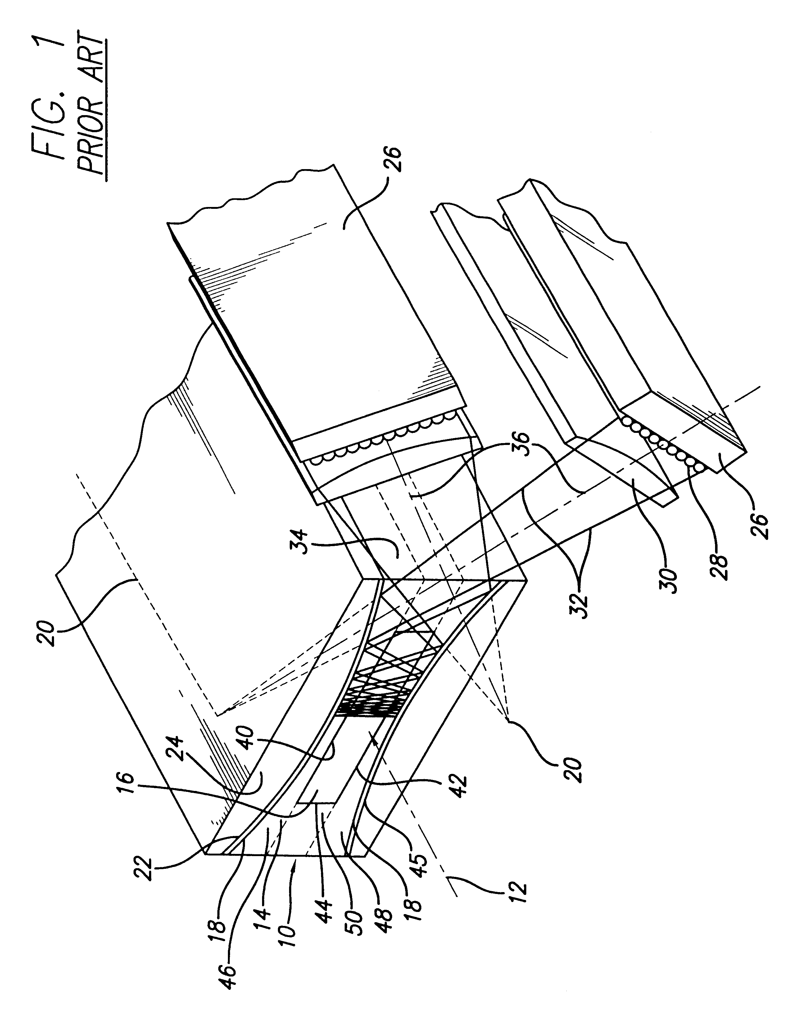
FIG. 1 is a schematic perspective view of a slab laser pump cavity with integral concentrator implemented in accordance with the teachings of the above-reference '064 application. The apparatus is an edge-pumped configuration which employs a slab-shaped laser pump cavity...


PUM


Abstract

A concentrator including a volume of at least partially transmissive material and a plurality of facets disposed at at least one surface thereof. Each of the facets is disposed at a position dependent angle relative to the surface effective to cause an internal reflection of energy applied to the layer whereby the density of the applied energy varies as a function of position. In the illustrative implementation, the volume is an active medium, i.e., a slab. The slab has substantially parallel, planar upper and lower surfaces and first and second edges therebetween. A plurality of cladding layers are disposed on the upper and lower surfaces of the slab. The facets are provided in the cladding layers on the upper and lower surfaces of the slab and angled as a function of distance relative to the first or the second edge. The facets provide a Fresnel reflecting surface or a binary optic surface.

Description

1. Field of the InventionThe present invention relates to lasers. More specifically, the present invention relates to systems and methods for pumping solid-state slab lasers.2. Description of the Related ArtDoped-insulator slab lasers are solid state lasers that are used in a variety of applications requiring moderate to high optical output power. The slab lasing material is typically comprised of a host crystal doped with an ion, such as, for example, ytterbium doped yttrium aluminum garnet (Yb:YAG). High power slab lasers employing lasing media with high aspect ratio slab configurations have traditionally been optically pumped through the broad slab faces with one or more linear flashlamps and have been cooled either by forced convection or conduction through the same faces. (Pumping is the process by which an active (lasing) medium is excited to achieve a population inversion. The population inversion is a condition by which energy is stored in the medium with sufficient gain to ...

Claims


Application Information

Patent Timeline
Patent Type & Authority Patents(United States)
IPC IPC(8): H01S3/0941H01S3/06
CPCH01S3/09415H01S3/0606H01S3/0612H01S3/094084H01S3/0617
Inventor BYREN, ROBERT W.ROCK, DAVID F.TSAI, CHENG-CHIH
Owner RAYTHEON CO
Why Eureka
Try Eureka