Method for starting an internal combustion engine, in particular on a motor vehicle

a technology for internal combustion engines and motor vehicles, which is applied in the direction of engine starters, electric control, ignition automatic control, etc., can solve the problems of failure of the first start attempt of the engine, the failure of the first start attempt, etc., and achieve the effect of increasing the acceleration capacity

Inactive Publication Date: 2003-07-08
ROBERT BOSCH GMBH
View PDF7 Cites 45 Cited by
  • Summary
  • Abstract
  • Description
  • Claims
  • Application Information

AI Technical Summary

Benefits of technology

Thereafter, fuel is injected into that cylinder whose piston is located in the reversal point in the compression phase and ignited shortly ahead or at top dead center of this piston. This is that cylinder into which, at the start, the first injection has taken place which has generated the backward movement. This affords the advantage that uncombusted mixture from the first combustion is now completely combusted. The crankshaft is further accelerated in the forward direction by the renewed injection and ignition which is present.
In a second embodiment, the injection and/or the ignition is carried out in such a manner that the piston

Problems solved by technology

Under unfavorable conditions, such as when there is an unfavorable crankshaft angle, it is, however, possible that at least a first start attempt

Method used


Image

  • Method for starting an internal combustion engine, in particular on a motor vehicle
  • Method for starting an internal combustion engine, in particular on a motor vehicle
  • Method for starting an internal combustion engine, in particular on a motor vehicle

Examples


Embodiment Construction

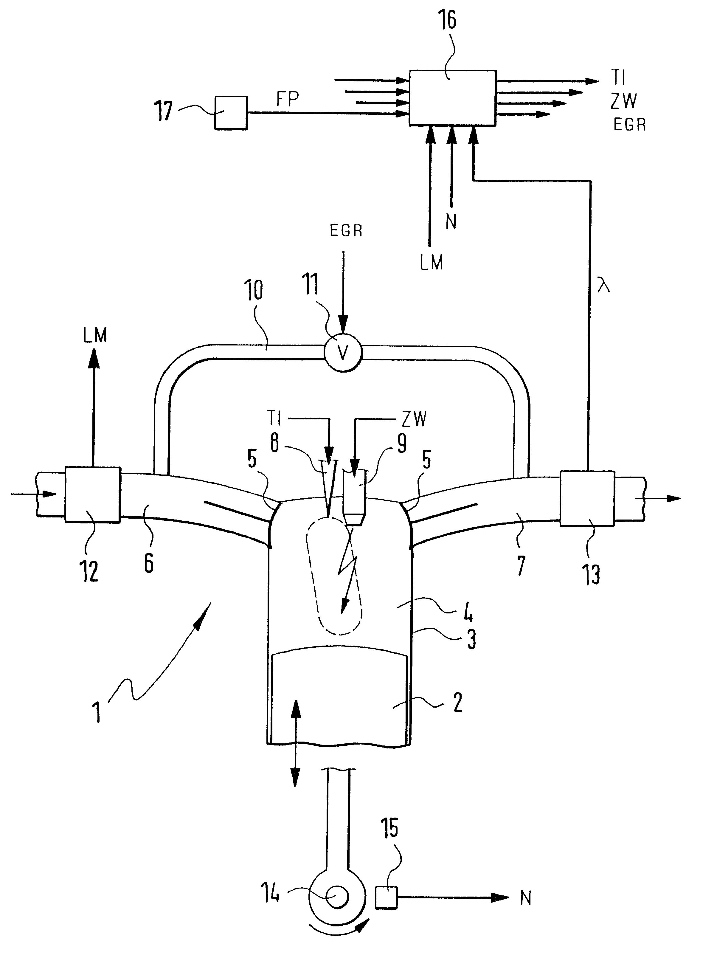
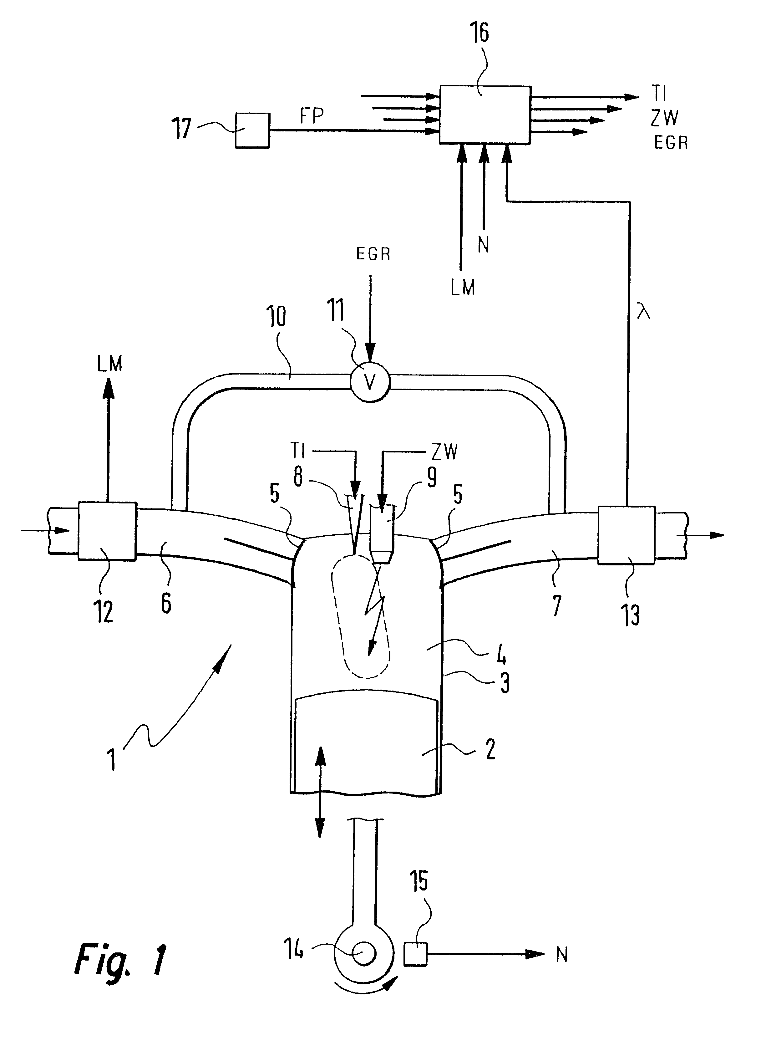
In FIG. 1, an internal combustion engine 1 is shown wherein a piston 2 is movable back and forth in a cylinder 3. The cylinder 3 is provided with a combustion chamber 4 to which an intake manifold 6 and an exhaust-gas pipe 7 are connected via valves 5. Furthermore, an injection valve 8, which can be driven by a signal TI, and a spark plug 9, which can be driven by a signal ZW, are assigned to the combustion chamber 4. The exhaust-gas pipe 7 is connected via an exhaust-gas recirculation line 10 and an exhaust-gas recirculation valve 11 to the intake manifold 6. The exhaust-gas recirculation valve 11 can be controlled by a signal EGR.

The intake manifold 6 is provided with an air mass sensor 12 and the exhaust-gas pipe 7 is provided with a lambda sensor 13. The air mass sensor 12 measures the oxygen mass of the fresh air, which is supplied to the intake manifold 6 and generates a signal LM in dependence thereon. The lambda sensor 13 measures the oxygen content of the exhaust gas in the...


PUM


Abstract

An internal combustion engine, especially an engine for a motor vehicle, is described which is provided with a piston, which is movable in a cylinder and acts on a crankshaft. The piston can run through an intake phase, a compression phase, a work phase and a discharge phase. A control apparatus is provided with which the fuel can be injected directly into a combustion chamber delimited by the cylinder and the piston in a first operating mode during a compression phase or in a second operating mode during an intake phase. The control apparatus is so configured that, for starting the engine at standstill of the crankshaft, fuel can be injected into that cylinder (no. 1) whose piston is disposed in the compression phase and can be ignited (20, 21) so that the crankshaft moves rearwardly (22).

Description

The invention relates to a method for starting an internal combustion engine, especially of a motor vehicle, wherein the engine has a piston movable in a cylinder with the piston acting on a crankshaft. The piston can run through an intake phase, a compression phase, a work phase and a discharge phase. In the method, the fuel can be injected directly into a combustion chamber in a first operating mode during a compression phase or in a second operating mode during an induction phase. The combustion chamber is delimited by the cylinder and the piston. Furthermore, the invention relates to a corresponding internal combustion engine as well as a corresponding control apparatus, especially for a motor vehicle.BACKGROUND INVENTIONA method of this kind as well as an internal combustion engine of this kind and a control apparatus of this kind are all known from U.S. Pat. No. 6,050,232.There, during starting, the first injection is undertaken into that cylinder whose piston is in the work p...

Claims


Application Information

Patent Timeline
IPC IPC(8): F02N9/02F02N17/00F02N9/00F02P5/15F02D41/02F02D41/06F02D43/00F02D45/00F02N11/08F02N19/00F02N99/00
CPCF02N9/02F02N19/005F02N99/006F02D2250/06F02N2019/007
Inventor SIEBER, UDO
Owner ROBERT BOSCH GMBH
Why Eureka
Try Eureka