Method and apparatus for measuring viewing angle characteristic and positional characteristic of luminance

a technology of luminance and viewing angle, applied in the field of lcd displays, can solve the problems of inability to obtain accurate information of pixels, inability to reduce the average intensity of light per pixel, and high cost of apparatus, so as to prevent the loss of ccd sensitivity, increase the density of ccd, and increase the effect of sensitivity

Inactive Publication Date: 2003-07-08
MITSUBISHI ELECTRIC CORP +1
View PDF10 Cites 14 Cited by
  • Summary
  • Abstract
  • Description
  • Claims
  • Application Information

AI Technical Summary

Benefits of technology

to provide an improved apparatus attaining a desired resolution in the measurement of angular luminance distribution by increasing the intensity of light falling on each CCD pixel as much as possible, thereby preventing the loss of sensitivity of the CCD device caused by increasing CCD density on the CCD device and preventing loss of the accuracy of the measurement due to condensation effect of the condensing lens.

Problems solved by technology

However, if the pixel density is increased in an attempt to raise the resolution, the average intensity of light per one pixel is disadvantageously decreased.
Furthermore, a large aperture lens is needed to obtain a better viewing-angle characteristic, which makes the apparatus costly.
The prior art apparatus of FIG. 17 has a further disadvantage that accurate information of pixels cannot be obtained due to the fact that the information, obtained in the form of image on the CCD array 47, includes angular characteristics of the pixels.
However, in the apparatus of FIG. 17, the information carried by the light from the central region of the LCD panel onto the CCD array is greatly affected by the information carried by the light from peripheral regions of the LCD panel.
Hence, the apparatus of FIG. 17 has a drawback that must be overcome if it is usable as an apparatus for evaluating unevenness of pixels.

Method used


Image

  • Method and apparatus for measuring viewing angle characteristic and positional characteristic of luminance
  • Method and apparatus for measuring viewing angle characteristic and positional characteristic of luminance
  • Method and apparatus for measuring viewing angle characteristic and positional characteristic of luminance

Examples


first embodiment

the inventive apparatus will now be described.

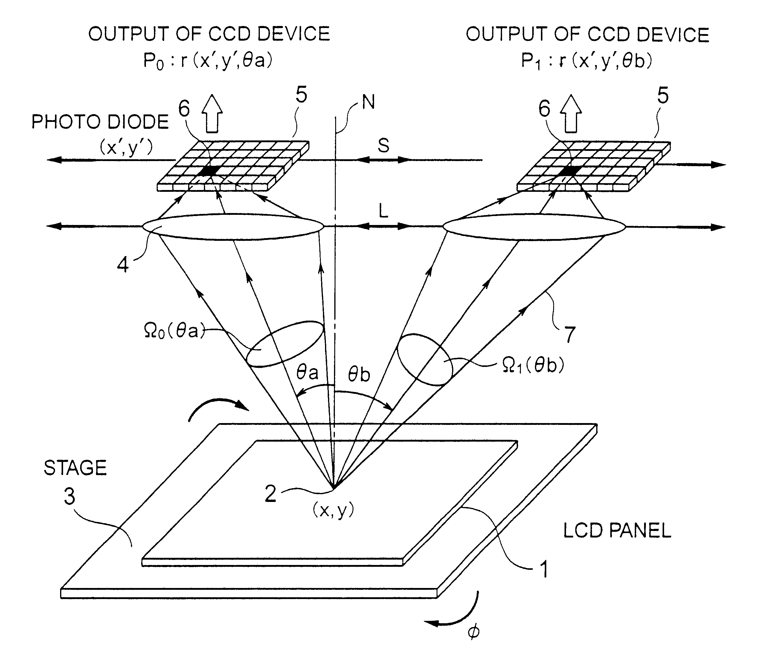
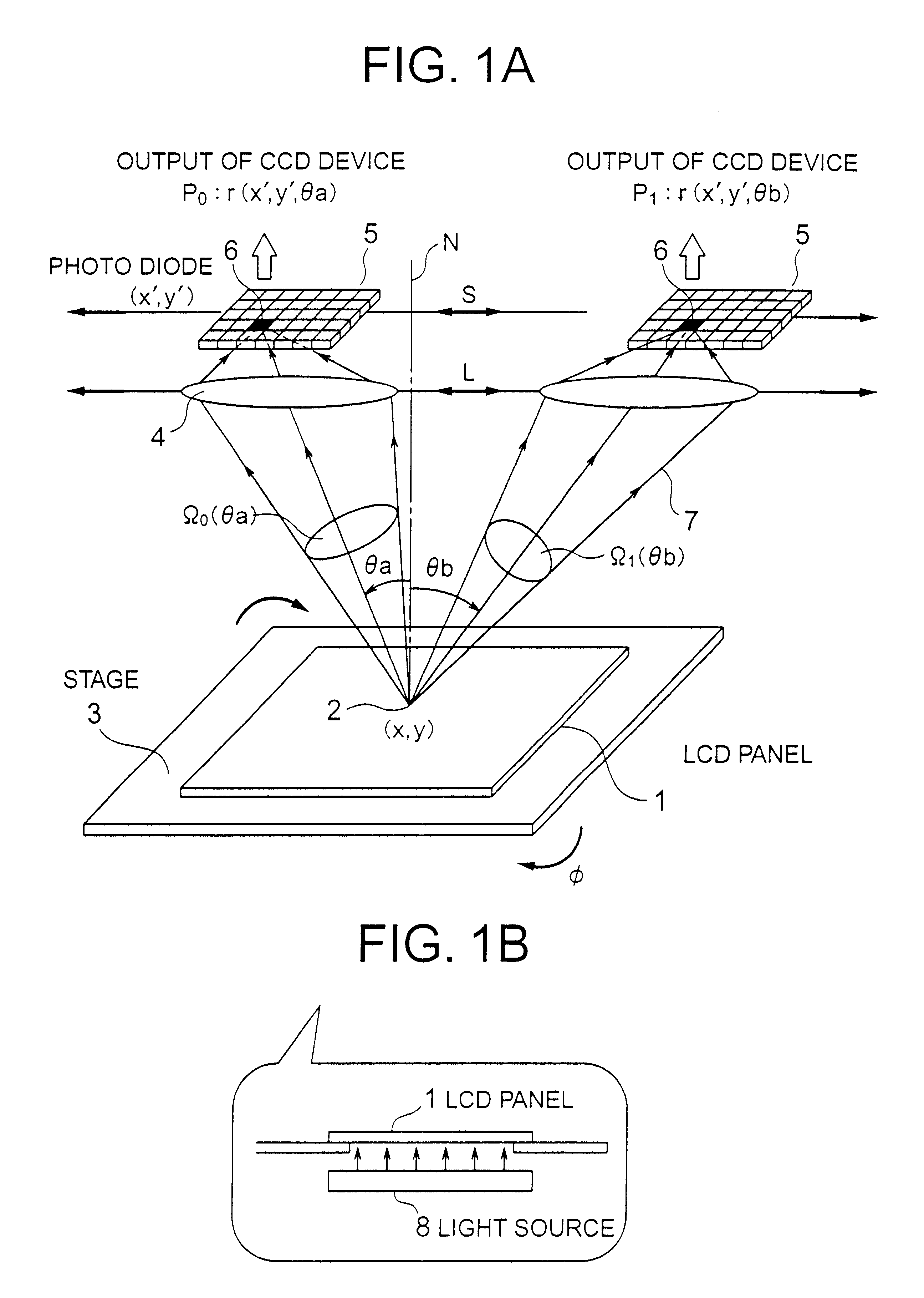
Referring to FIG. 1A, there is shown a bird-eye view of a first luminance distribution measurement apparatus of the invention. FIG. 1B shows a cross sectional view of the stage section of the apparatus shown in FIG. 1A. As shown in FIG. 1A, the apparatus includes an LCD panel 1 which is the radiant object under measurement, a radiant area of the 2 (which is an LCD pixel in this example), radiating beams of light 7 from the radiant area (LCD pixel) 2, a stage 3 for translating the LCD panel, a lens 4 for receiving and condensing the light, a CCD serving as an imaging device, and photodiodes 6 of the CCD device. Shown in FIG. 1B by a reference numeral 8 is a light source of the LCD panel of the 1.

In the EMBODIMENT 1 shown in FIG. 1A, the CCD device 5 is positioned such that the beams of light emerging from the pixel 2 at the coordinate (x, y) of the LCD panel 1 forms its real image at the coordinate (x', y') on the plane of the photodiodes...

embodiment 2

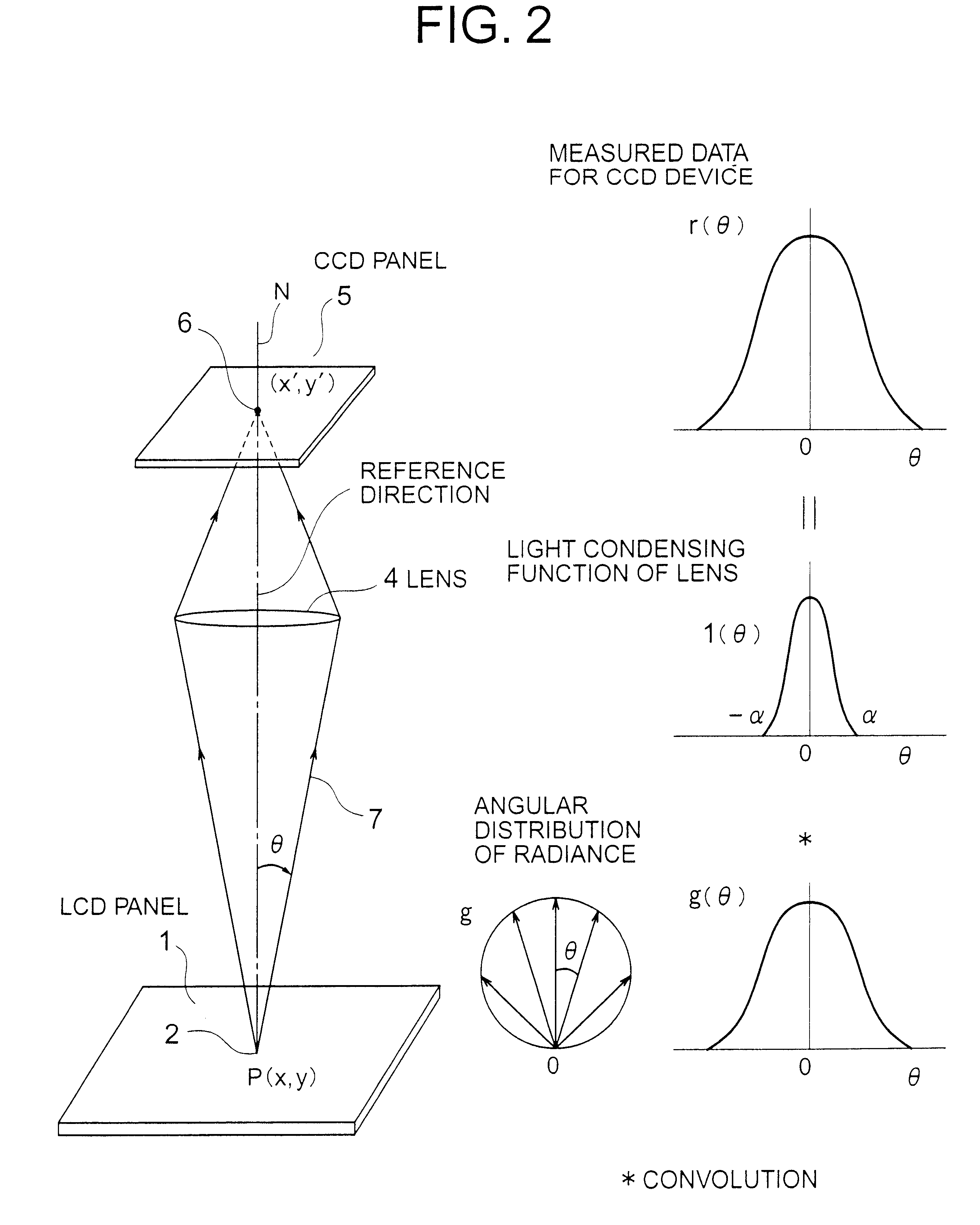
FIG. 8 is a bird-eye view of a second apparatus for measuring the luminance distribution of an LCD panel according to the invention. In the arrangement shown in FIG. 8, the lens 4 serving as the condensing element is rotated by the condensing device translation mechanism (not shown) about the radiant area 2 in the direction L, keeping constant the solid angle subtended by the lens 4 as viewed from the radiant area 2. At the same time the CCD device is also rotated by the imaging device translation mechanism about the radiant area 2 in the direction S as shown, keeping thereon the image of the radiant area 2 formed. The luminance distribution function g(.theta.) of the LCD panel 1 can be obtained from Eq. (6) as described in connection with EMBODIMENT 1. In this case the condensing function .vertline.(.theta.) is constant, since the solid angle subtended by of the lens 4 as viewed from the radiant area 2 is constant at any angle .theta., so that the accuracy of the data obtained in t...

embodiment 3

It is noted that in the embodiment 1 the angle subtending the lens 4 from the radiant area 2 varies with the position of the lens 4. In this instance also, highly accurate evaluation of the luminance may be obtained by making a correction of the luminance as described below.

Assuming in FIG. 1A that .theta. is the angle subtended the lens 4 from an radiant area 2 of the LCD panel with respect to the normal line N at the radiant area; P0 is the output power of the CCD device and .OMEGA.0 is the solid angle (steradian) subtended the lens when the lens of the 4 is located at the angle .theta.a; P1 is the output CCD device; and .OMEGA.1 is the solid angle subtended the lens 4 when the lens 4 is positioned at angle .theta.b, then the output power P1' CCD device after the correction of P1 with respect to the lens position .theta.a is given by the following formula.

P1'=P1.times.(.OMEGA.0 / .OMEGA.1) (9)

A decrease in flux of incident light to the lens 4 due to a decrease in solid angle of the ...


PUM

PropertyMeasurementUnit
degree of freedomaaaaaaaaaa
luminanceaaaaaaaaaa
solid angleaaaaaaaaaa

Abstract

An apparatus is provided for measuring viewing angle characteristic of luminance and positional characteristic of a radiant object under measurement, by moving a condensing device and an imaging device relative to the object. The apparatus includes a first mechanism for moving the light receiving elements of the condensing device while keeping constant the solid angle subtended by the light receiving element at the radiant area. A second mechanism is provided for moving the imaging device in association with the condensing device, while maintaining thereon the image of the radiant area. A memory is provide. A circuit is provided for calculating viewing angle dependent and position dependent characteristics. A display device is provided for displaying radiance characteristic and distribution characteristic of the object and the result of evaluation of the calculated characteristic of luminance.

Description

1. Field of the InventionThe invention relates to an LCD displays or a semimanufactured goods therefor for use with terminal devices such as notebook type personal computers (PCs) and cellular phones, and more particularly to the methods and apparatuses of measuring viewing angle characteristics and positional characteristics of luminance of such products.2. Description of the Prior ArtA typical prior art apparatus for measuring angular distribution of luminance (also referred to as luminance distribution measurement apparatus) is disclosed in FIGS. 15, 16, and 17 of Japanese Patent Early Publication of the 6-94515. The apparatus shown in FIG. 15 includes a radiant object in the form of liquid crystal display (LCD) panel 41 having radiant areas (pixels), a light source 42, and a photometer 43 for measuring the intensity of light. The apparatus shown in FIG. 16 includes a mounting table 44, a lens 45, and an array of charge coupled device (CCD) 46. The apparatus shown in FIG. 17 incl...

Claims


Application Information

Patent Timeline
Patent Type & Authority Patents(United States)
IPC IPC(8): G01J1/04G01J1/00G01J1/38G01J1/42G01M11/00G02F1/13
CPCG01J1/04G01J1/0403G01J1/0411G01J1/0414G01J1/4228G01J1/0242
Inventor KUBOTA, HIROSHIEGASHIRA, YOSHIYAFURUSE, TOMOAKIHIROSE, SATOSHI
Owner MITSUBISHI ELECTRIC CORP
Why Eureka
Try Eureka