Electret capacitor microphone

a capacitor microphone and capacitor technology, applied in the direction of electrical transducers, selectrostatic transducers of electrets, semiconductor devices, etc., can solve the problems of large number of parts, inability to reduce the thickness of the crimping portion and the pad electrode, and inability to meet the demand for a reduction in size and weight of the whole microphon

Inactive Publication Date: 2003-07-15
KYOCERA CORP
View PDF11 Cites 188 Cited by
  • Summary
  • Abstract
  • Description
  • Claims
  • Application Information

AI Technical Summary

Benefits of technology

Another object of the present invention is to provide an electret capacitor microphone capable of being assembled with mechanical fixation and electrical connection of parts carried out readily.
Furthermore, the square casing can cause the microphone to be easily handled in a manufacturing process and the completed microphone to be positioned precisely on a wiring board.

Problems solved by technology

However, in the conventional microphone technique, a large number of parts have been required and the thickness the crimping portion and the pad electrode could not be reduced.
Moreover, in the conventional microphones, since the dielectric and the printed circuit board have been utilized, it has been impossible to satisfy the demand for a reduction in size and weight of the whole microphone.
Conventional electret capacitor microphones are not suitable for mass-production and have had a low productivity.
In the conventional electret capacitor microphones, since the metal casing is crimped with a substrate, and then the uncertainty of fixation of each part causes microphone failure in use and reduces the yield of the microphone products.
In addition, the cylindrical metal casing 5 is hard to handle for mounting and to position.
Furthermore, even if a sound hole is to have a complicated shape, processing is hard.
The metal casing 5 is apt to transmit a surrounding mechanical vibration, has an adverse influence on the diaphragm and supplies a noise to an electric signal, resulting in a deterioration in microphone performance.
Therefore, it has been hard to solder the microphone onto the printed circuit board by heating.

Method used


Image

  • Electret capacitor microphone
  • Electret capacitor microphone
  • Electret capacitor microphone

Examples


first embodiment

In this example, a solid state device is provided on a bottom below a diaphragm and a fixed electrode in the same hollow portion accommodating the diaphragm and the fixed electrode.

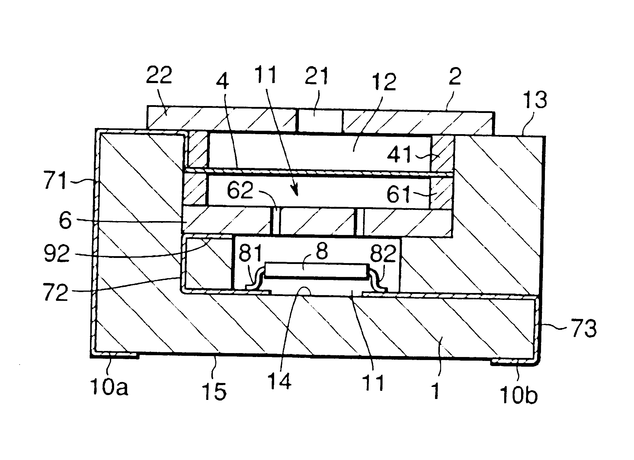
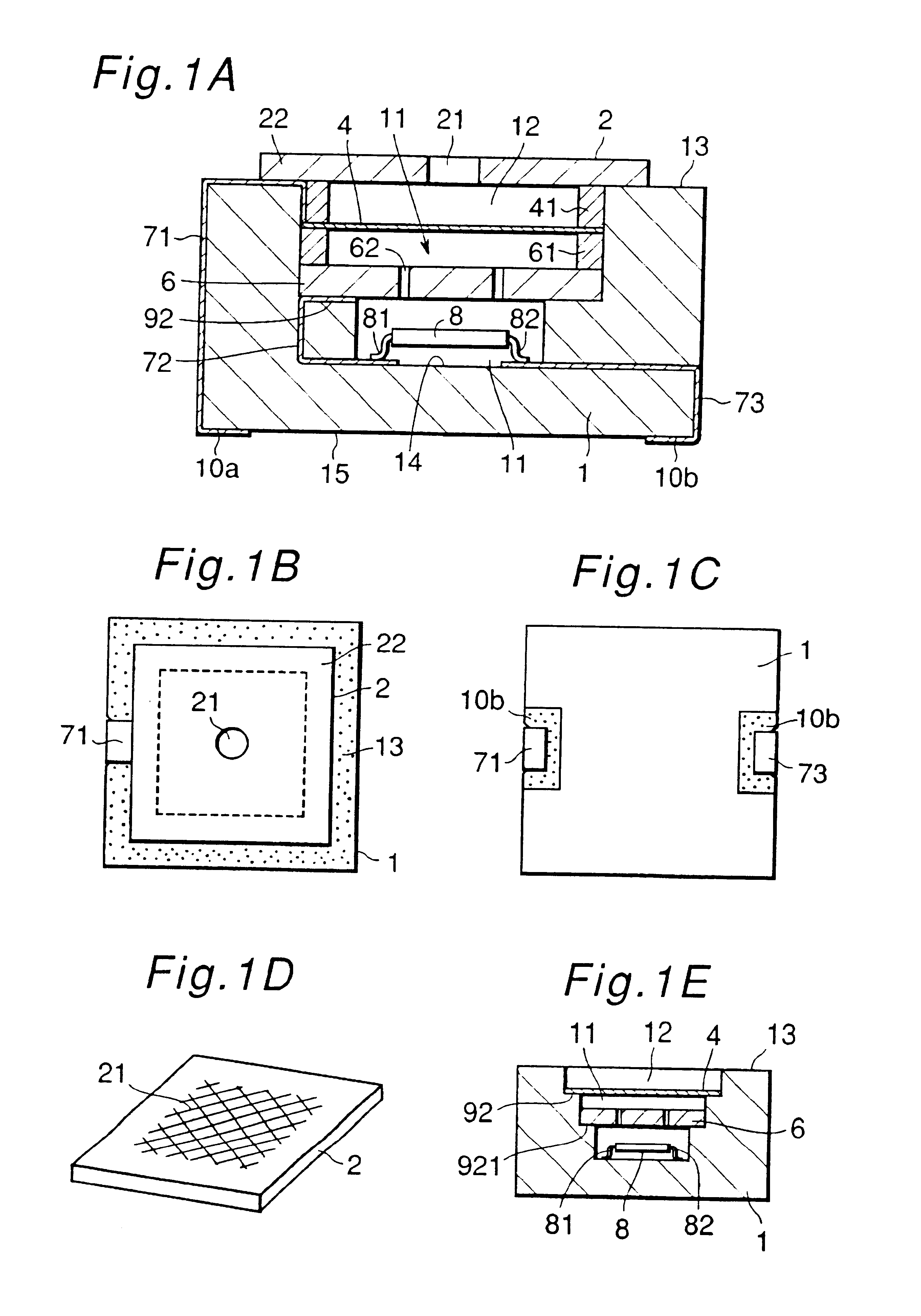
A microphone shown in FIG. 1A utilizes a rectangular box-shaped casing 1, and a hollow portion 11 in the casing 1 has a rectangular section and the opposite side of the bottom is opened. A stepped portion 92 Is formed on the inner surface of the hollow portion 11.

A fixed electrode 6 is mad of a metal with through holes 62 passing therethrough and is mounted on the stepped portion 92 and is fixed thereto, and a diaphragm 4 is mounted with a very small capacitor gap through a ring-shaped dielectric spacer 61 above the fixed electrode 6,thereby constituting a capacitor. A peripheral edge portion 22 is bonded and fixed to an upper surface 13 of the opening of the hollow portion 11 through a ring spacer 41.

Furthermore, a solid state device 8 is located on a bottom 14 in the hollow portion 11 closer to the bott...

second embodiment

Second Embodiment

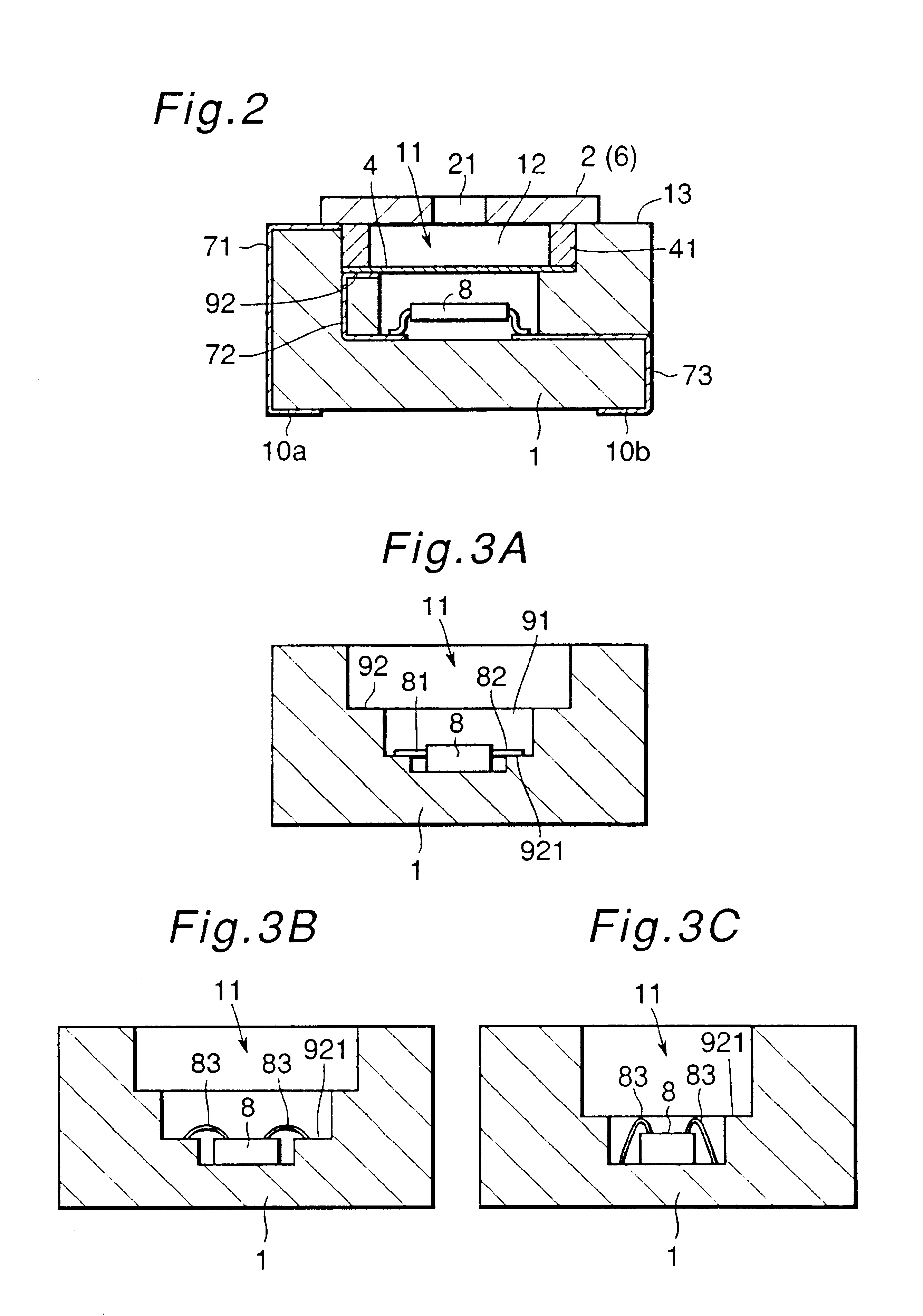
In the present embodiment, a fixed electrode is also used as a cover. In the example shown in FIG. 2, an opening 12 of a casing 1 is covered with a metal cover 2 having a sound hole fixed to an upper surface 13, and the back side of the cover is provided with a diaphragm 4 through a dielectric gap spacer 41. The diaphragm 4 is fixed to a stepped portion 92 in a hollow portion. The cover 2 is connected to a pad electrode 10a through a conductive path 71 provided on an outer surface, and the diaphragm 4 is connected to a pad electrode 10b through a conductive path 72, a solid state device 8 and a conductive path 73 as described above.

In the present embodiment, the cover 2 is also used as the fixed electrode 6 to detect a change in an electrostatic capacity between the cover 2 (fixed electrode 6) and the diaphragm 4. Consequently, the number of parts can be more decreased and a size can be more reduced as compared with those in FIG. 1.

Next, the structure of attachment ...

third embodiment

FIG. 6A shows a microphone comprising two independent and adjacent hollow portions 11a and 11b separated though partition walls in a casing 1 made of a dielectric. The combination of a diaphragm 4 and a fixed electrode 6 is provided in the hollow portion 11a and a solid state device 8 is provided in the hollow portion 11b. In this example, both hollow portions 11a and 11b are covered with one plate-shaped cover 2.

In the hollow portion 11, the fixed electrode 6 is provided on a bottom face, a stepped portion 92 is formed, and a diaphragm 4 is provided on the upper surface of the stepped portion through a capacitance gap with respect to the fixed electrode 6. A thin film made of an electret material having a metal layer formed thereon is utilized for the diaphragm 4. The solid state device 8 is directly bonded to the bond face in the hollow portion 11b. An amplifier circuit or the like is formed on the solid state device 8.

The cover 2 serves to close the two hollow portions 11a and 11...


PUM


Abstract

An electret capacitor microphone is constituted by a surface conductive diaphragm, a fixed electrode provided opposite to the diaphragm at a regular interval and a solid state device for converting, into an electric signal, a voice given to the diaphragm with a change in an electrostatic capacity between the diaphragm and the fixed electrode. The microphone comprises a dielectric casing having a bottomed hollow portion for accommodating the diaphragm, the fixed electrode and the solid state device. Since the casing itself is dielectric, it does not deed to accommodate a special dielectric or a board for the solid state device but can be directly provided in the hollow portion. Therefore, the microphone can be very small-sized and thinned. The hollow portion of the casing has a stepped portion and the diaphragm or the fixed electrode is fixed onto the stepped portion. The hollow portion of the casing has a rectangular cross section and the external shape of the casing is rectangular, the parts can easily be provided in the hollow portion, an unnecessary space can be omitted, and a size can be reduced.

Description

1. Field of the InventionThe present invention relates to an electret capacitor microphone.2. Prior ArtElectret capacitor microphones are often provided with a thin diaphragm having a thin metal film facing toward an opening in a metal casing and a fixed electrode opposed thereto, and utilize the principal of a change in capacity between the diaphragm and the fixed electrode dependently on the vibration of the diaphragm due to a sound wave. The diaphragm utilizes a thin metallized electret material on a surface thereof, and a capacitor is formed between the diaphragm and the fixed electrode. A change in capacity is converted into a current or voltage change through a solid state device, the sound wave being fetched as an electric signal.Conventional electret capacitor microphones have been provided in a cylindrical metal casing 5 which disposes a diaphragm 4 made of an electret material with a metal layer deposited or other method on the surface and has a sound hole 21 in the centra...

Claims


Application Information

Patent Timeline
Patent Type & Authority Patents(United States)
IPC IPC(8): H04R19/00H04R19/01
CPCH04R19/016H01L2224/48091H01L2924/00014H01L2924/3025H01L2924/00
Inventor UNE, HIROSHI
Owner KYOCERA CORP
Why Eureka
Try Eureka