Thermally cured underlayer for lithographic application

a technology of lithographic and underlayer, which is applied in the direction of photosensitive materials, instruments, photomechanical equipment, etc., can solve the problems of standing wave effects, too absorbent and insensitive resists used at the higher wavelengths, and reduce resolution

Inactive Publication Date: 2003-08-26
ARCH CHEM INC
View PDF9 Cites 30 Cited by
  • Summary
  • Abstract
  • Description
  • Claims
  • Application Information

AI Technical Summary

Problems solved by technology

The problem with using deep UV wavelengths is that resists used at the higher wavelengths were too absorbent and insensitive.
One problem is standing wave effects, which occur when monochromatic is reflected off the surface of a reflective substrate during exposure.
The formation of standing waves in the resist reduces resolution and causes linewidth variations.
For example, standing waves in a positive resist have a tendency to result in a foot at the resist / substrate interface reducing the resolution of the resist.
In addition, chemically amplified resist profiles and resolution may change due to substrate poisoning.
However, in order to decrease absorbance of the chemically amplified resist, aromatic groups, such as those in novolaks had to be removed, which in turn decreased the etch resistance.
Even though the undercoat attenuates standing waves and substrate poisoning, it poses other problems.
If there is intermixing between the top and undercoat layers, the resolution and sensitivity of the top resist layer will be detrimentally affected.
In addition, if there is a large difference in the index of refraction between the chemical amplified resist and the undercoat layer, light will reflect off the undercoat layer causing standing wave effects in the resist.
Another problem with undercoating layers is that they are sometimes too absorbent because of incorporation of aromatic groups.
If the undercoat layer is too absorbent, the reflected light needed for alignment is too attenuated to be useful.
However, if the undercoat layer is not absorbent enough, standing waves may occur.
In addition, some undercoats have very poor plasma etch resistance to plasma chemistry.
The problem with UV cross-linking undercoat layers is that they require long exposure times to form sufficient cross-links.
The long exposure times severely constrain throughput and add to the cost of producing integrated circuits.
The UV tools also do not provide uniform exposure so that some areas of the undercoat layer may be cross-linked more than other areas of the undercoat layer.
In addition, UV cross-linking exposure tools are very expensive and are not included in most resist coating tools because of expense and space limitations.
However, the problem with these undercoat layers is that they require high curing temperatures and long curing times before the top layer can be applied.
(a) solubility and compatibility of the current generation 248-nm TCU in common edge-bead removing (EBR) solvents such as propylene glycol mono methyl ether acetate (PGMEA), ethyl lactate (EL), ethyl ethoxy propionate (EEP), and the like;
(b) standing waves presumably, due to less than optimum match of optical parameters (n and k) of the undercoat with substrate and imaging layer (IL); and
(c) scumming at the TCU / imaging layer (IL) interface.
In the proposed TCU compositions, although optical constants were able to be reasonably matched, standing waves and scumming at the TCU / IL interface could not be totally eliminated.
Additionally, while the use of methyl methoxy propionate (MMP) has been proposed as utilizable for solubilizing the TCU polymer and to address edge bead removing characteristics, MMP is not generally acceptable as a lithographic solvent.

Method used


Image

  • Thermally cured underlayer for lithographic application
  • Thermally cured underlayer for lithographic application
  • Thermally cured underlayer for lithographic application

Examples


polymer example 1

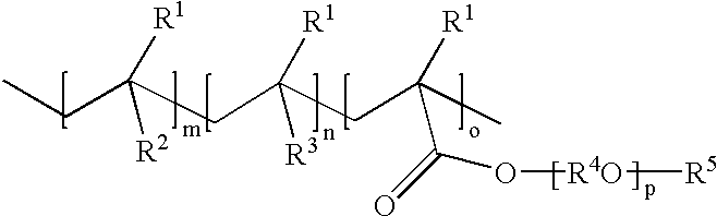
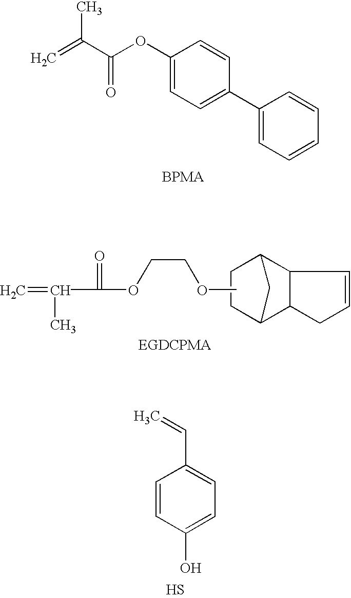
The mixture of monomers [4-biphenyl methacrylate (72.37 g, 0.303 mol), acetoxy styrene (10.56 g, 0.065 mol) and ethylene glycol dicyclopentenyl ether methacrylate (17.07 g, 0.065 mol)] and initiator VAZO 67 (6.00 g, 6.0 wt % vs monomers) and chain transfer agent 1-dodecanethiol (1.80 g, 30 wt % vs initiator) were polymerized according to the general procedure above. Transesterification employed 4.0 g sodium methoxide solution. Yield: 91.3 g, 94%. M.sub.w =14,666; M.sub.w / M.sub.n =1.92. 5% weight loss at 310.degree. C., Tg: 128.degree. C. composition of polymers, mol %: 69% biphenyl methacrylate units; 16% hydroxystyrene units and 15% ethyleneglycol dicyclopentenyl ether methacrylate units.

polymer example 2

The mixture of monomers [4-biphenyl methacrylate (62.74 g, 0.263 mol), acetoxy styrene (14.23 g, 0.087 mol) and ethylene glycol dicyclopentenyl ether methacrylate (23.03 g, 0.087 mol)] and initiator VAZO 67 (6.00 g, 6.0 wt % vs monomers) and chain transfer agent 1-dodecanethiol (1.80 g, 30 wt % vs initiator) were polymerized according to the general procedure above. Tranesterification employed 5.0 g sodium methoxide solution. Yield: 91.5 g, 95%. M.sub.w =13,715; M.sub.w / M.sub.n =1.97. TGA: 5% weight loss at 305.degree. C.; Tg: 124.degree. C.; composition of polymers, mol %: 60% biphenyl methacrylate units; 19% hydroxystyrene units and 21% ethyleneglycol dicyclopentenyl ether methacrylate units.

polymer example 3

The mixture of monomers [4-biphenyl methacrylate (54.09 g, 0.227 mol), acetoxy styrene (22.09 g, 0.136 mol) and ethylene glycol dicyclopentenyl ether methacrylate (23.82 g, 0.09 mol)] and initiator VAZO 67 (6.00 g, 6.0 wt % vs monomers) and chain transfer agent 1-dodecanethiol (1.80 g, 30 wt % vs initiator) were polymerized according to the general procedure above. Transesterification employed 6.0 g sodium methoxide solution. Yield: 85.5 g, 91%. M.sub.w =11,262 / 1.88; M.sub.w / M.sub.n =1.88; TGA: 5% weight loss at 300.degree. C.; Tg: 118.degree. C. composition of polymers, mol %: 51% biphenyl methacrylate units; 28% hydroxystyrene units and 21% ethyleneglycol dicyclopentenyl ether methacrylate units.


PUM

PropertyMeasurementUnit
wavelengthaaaaaaaaaa
temperaturesaaaaaaaaaa

Abstract

Thermally cured undercoat for use in lithography of a thermally cured composition comprising a hydroxyl-containing polymer, an amino cross-linking agent and a thermal acid generator, wherein the hydroxyl containing polymer is a polymer comprising units m, n and o of the following formula:wherein R1 is H or methyl; R2 is a substituted or unsubstituted C6-C14 aryl acrylate or C6-C14 aryl methacrylate group wherein the substituted groups may be phenyl, C1-4 alkyl or C1-4 alkoxy; R3 is a hydroxyl functionalized C1-C8 alkyl acrylate, methacrylate or C6-C14 aryl group, R4 is a C1-C10 linear or branched alkylene; p is an integer of from 1 to 5 with the proviso that there are no more than thirty carbon atoms in the [-R4O-]p; R5 is a C1-C10 linear, branched or cyclic alkyl, substituted or unsubstituted C6-C14 aryl, or substituted or unsubstituted C7-C15 alicyclic hydrocarbon; and m is about 40 to 70, n is about 15 to 35 and o is about 15 to 25.

Description

The present invention relates to deep UV lithography used in semiconductor manufacturing and more particularly to undercoat layers for chemically amplified bilayer resist systems.BACKGROUND TO THE INVENTIONIntegrated circuit production relies on the use of photolithographic processes to define the active elements and interconnecting structures on microelectronic devices. Until recently, g-line (436 nm) and l-line (365 nm) wavelengths of light have been used for the bulk of microlithographic applications. However, in order to achieve smaller dimensions of resolution, the wavelength of light used for microlithography in semiconductor manufacturing has been reduced into the deep UV regions of 254 nm and 193 nm. The problem with using deep UV wavelengths is that resists used at the higher wavelengths were too absorbent and insensitive. Thus, in order to utilize deep UV light wavelengths, new resist materials with low optical absorption and enhanced sensitivities were needed.Chemically a...

Claims


Application Information

Patent Timeline
Patent Type & Authority Patents(United States)
IPC IPC(8): C08F212/14C08F212/32C08L29/02C08F216/00C08F216/02C08F216/12C08F212/00C08L29/00
CPCC09D133/14G03F7/11
Inventor DE, BINOD B.MALIK, SANJAYSPAZIANO, GREGORYBIAFORE, JOHN JOSEPHFOSTER, PATRICKSLATER, SIDNEY GEORGESTEINHAUSLER, THOMASBLAKENEY, ANDREW J.
Owner ARCH CHEM INC
Why Eureka
Try Eureka