
Piecewise linear calibration method and circuit to correct transfer function errors of digital to analog converters

a digital to analog converter and transfer function technology, applied in the field of digital to analog converters and methods for constructing and operating same, can solve the problems of high inl errors and the computation of transfer function errors of da

Inactive Publication Date: 2003-11-04
TEXAS INSTR INC
View PDF13 Cites 27 Cited by
  • Summary
  • Abstract
  • Description
  • Claims
  • Application Information

AI Technical Summary

Benefits of technology

In light of the above, therefore, it is an object of the invention to provide an improved digital-to-analog converter that has improved linearity and methods for constructing and operating same.
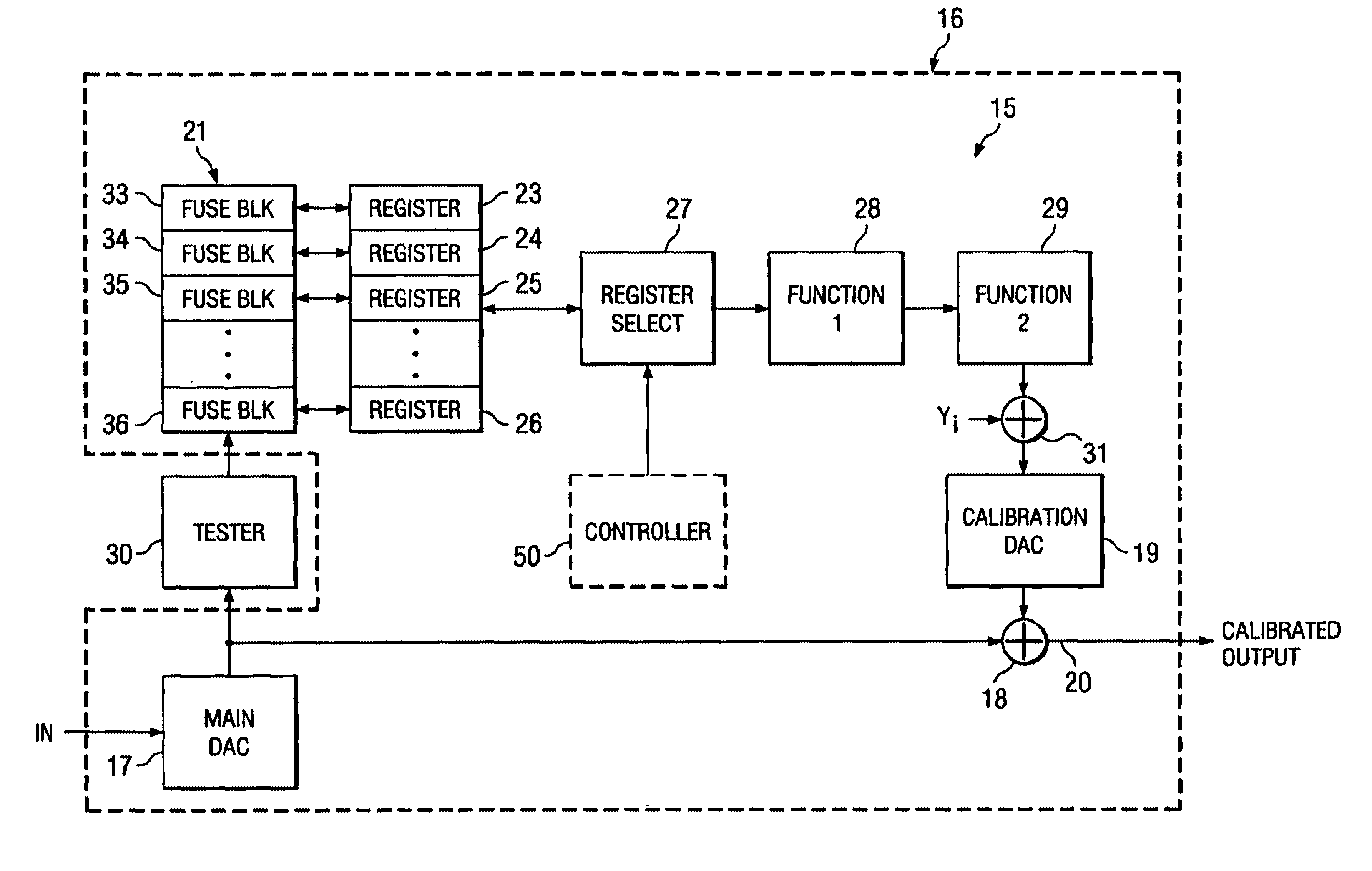
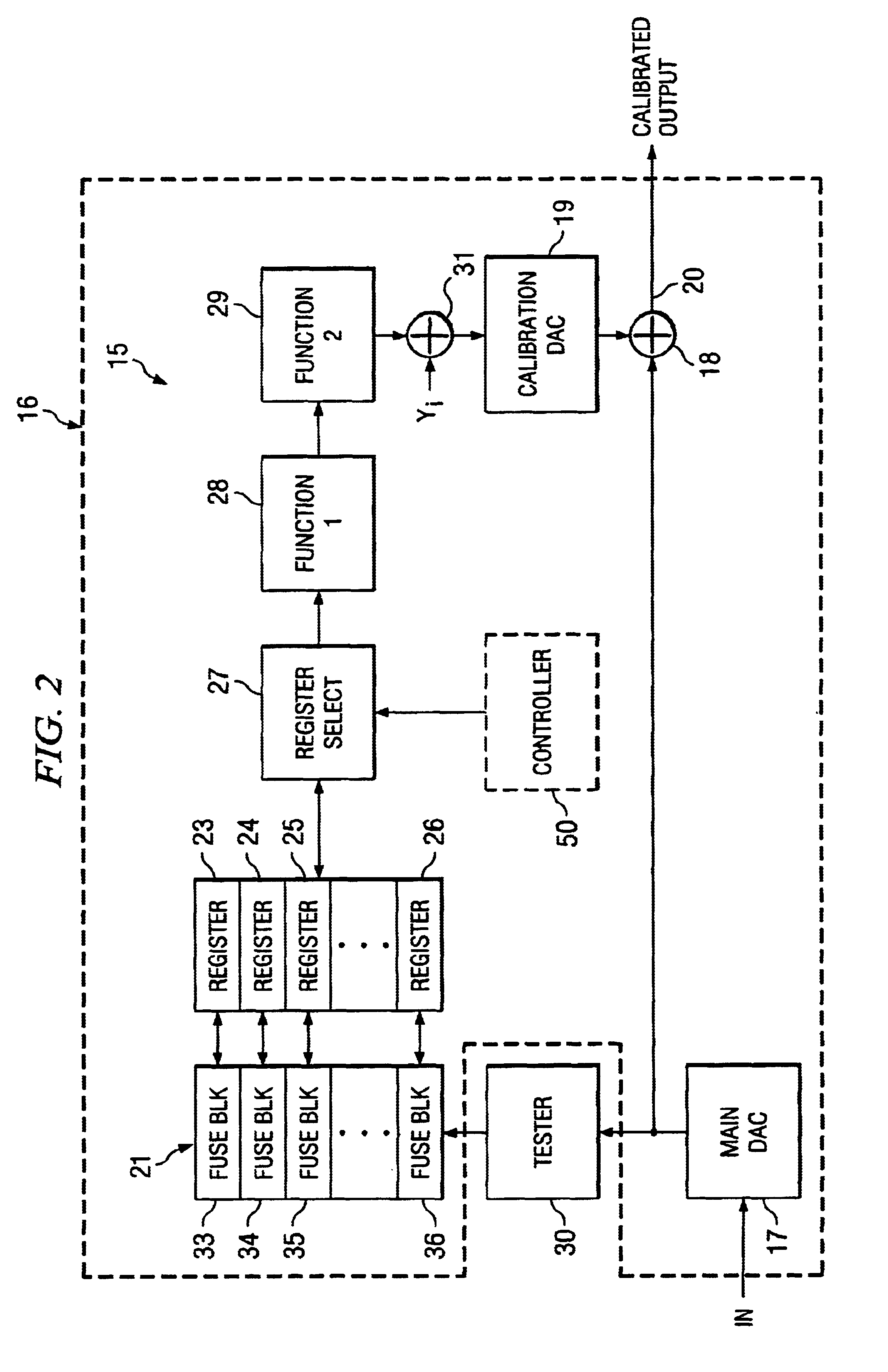
The present invention presents a digital-to-analog converter (DAC) with digital calibration to improve the overall integral nonlinearity (INL) performance. In one embodiment, the architecture includes of a 10 bit resistor string that decodes the 10 most significant bits (MSBs) and a 6 bit interpolating amplifier, which is used to decode the 6 least significant bits (LSBs). The DAC has digital calibration to improve INL characteristics. The resistor string architecture alone has good differential nonlinearity (DNL) characteristics, but suffers from high INL errors. Thus, transfer function errors of the DAC are computed during final test at specific points. The errors at these points are coded into permanent on-chip memory as control points. These control points then drive digital circuits that implement the math for piece-wise linear calibration waveform generation. A calibration DAC then sums the inverse of the error voltage to correct for the offset gain and linearity errors.
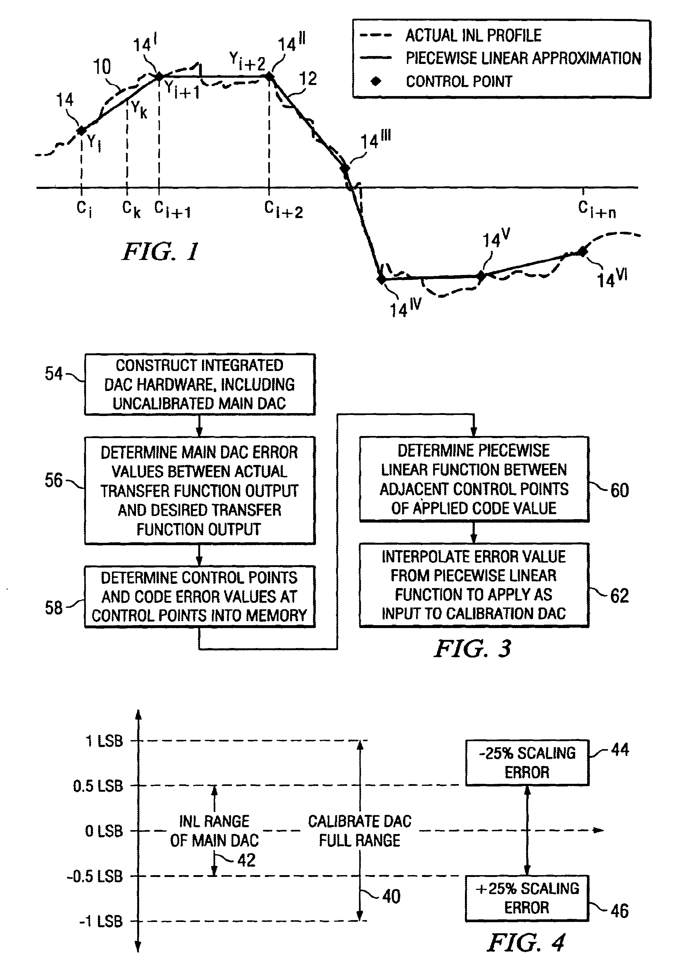
With reference now back to FIG. 1, a graph is shown of the actual integral nonlinearities (INL) of the main DAC 17 vs. input code word values. The graph of FIG. 1 compares a curve 10 of typical INL values of the signal output of an actual DAC constructed in accordance with a preferred embodiment of the invention with a piecewise linear approximation thereof 12. The piecewise linear approximation curve 12 is developed from the uncalibrated DAC having the INL profile 10, which follows the waveform shown, by selecting a set of codes, for example, conveniently based upon the waveshape of the measured, or actual, INL. Each code location X, and the corresponding INL value, Y, at selected codes constitutes a "control point", C.sub.i (Xi,Yi),C.sub.i+1 (X.sub.i+1,Y.sub.i+1) . . . C.sub.i+n (X.sub.i+n,Y.sub.i+n) 14, 14.sup.I . . . 14.sup.VI. The piecewise linear approximation 12 of the INL curve 10 then allows linear interpolation between each adjacent pairs of the control points 14 and 14.sup.I, . . . 14.sup.V and 14.sup.VI to approximate INL for any input code, for example, at point 14.sup.k corresponding to codeword C.sub.k. At this juncture, it should be noted that although the piecewise linear curves are shown as each being a single, continuous linear waveform, the waveforms may follow other piecewise linear curves as well. For example, the piecewise linear curves may be saw-tooth or other convenient waveform. Moreover, although presently piecewise linear INL approximations are preferred, linearity error can also be approximated and removed by implementing higher order polynomials, such as B-Splines, in the digital domain, as shrinking process geometries make this feasible. These approximation curves then can be used to construct and operate a calibrated DAC circuit, such as the calibrated DAC circuit of FIG. 5, using the steps shown in FIG. 3. The method and apparatus of this invention makes INL calibration possible through interpolation, without actually storing the INL values for most of the DAC inputs
It should be noted that as an option, either the difference in the control point values may be stored in the fuses, or, alternatively, the actual control point value may be stored. Storing the difference in control point values requires eight fuses for each control point (since the difference can range from 128 to 128 LSBs) amounting to a total of 72 fuses. This eliminates the need for a subtraction circuit. However, as can be seen from Equation 1 above, the actual value of each control point is required to evaluate the final expression. Thus, it may be desirable in some cases to store the actual control points rather than the difference.
In operation, to determine to identify which is the correct pair of control points between which the arbitrary input code lies, the first few MSBs of the input code and the control points may be compared. The arithmetic blocks 28 and 29 then perform division and multiplication functions, as follows. The calculation of slope of the applicable piecewise linear segment in Equation 1 requires division by the difference in the input code values of two adjacent control points. To make this division operation simple, the control points can conveniently be spaced uniformly with a known X axis spacing of "k times a power of 2". The difference in the x-axis of two adjacent control points is then a power of two, so the division will be a simple arithmetic right shift. The right shift operation can be achieved by just connecting the data buses in an appropriate manner, and thus the requirement of the shift register can be totally eliminated.

Problems solved by technology

The resistor string architecture alone has good differential nonlinearity (DNL) characteristics, but suffers from high INL errors.
Thus, transfer function errors of the DAC are computed during final test at specific points.

Method used


Image

  • Piecewise linear calibration method and circuit to correct transfer function errors of digital to analog converters
  • Piecewise linear calibration method and circuit to correct transfer function errors of digital to analog converters
  • Piecewise linear calibration method and circuit to correct transfer function errors of digital to analog converters

Examples


Embodiment Construction

- - -

VHDL LISTING

- - -

CODE 1--This block is a 8 bit register used for storing Y values (INL values)

library IEEE;use IEEE.Std_Logic_1164.all;use IEEE.Std_Logic_Unsigned.all;

--The entity is called memoryentity memory isport(clk,resetn:in std_logic;

Data_in:in std_logic_vector(6 downto 0);Data_out:out std_logic_vector(6 downto 0));end memory;architecture RTL of memory isbeginprocess(clk,resetn)beginif resetn=`0` thenData_out`0`);elsif clk'event and clk=`1` thenData_out<=Data_in;end if;end process;end;

CODE 2--This is the test bench for 8 bit register

library IEEE;use IEEE.Std_Logic_1164.all;use IEEE.Std_Logic_Unsigned.all;entity T_memory isend T_memory;architecture TEST of T_memory is component memory port (clk,resetn:in std_logic;Data_in:in std_logic_vector(6 downto 0);Dataout:out std_logic_vector(6 downto 0)); end component;signal clk,resetn:std_logic;signal Data_in, Data_out:std_logic_vector (6 downto 0);

begin - - -

--Instantiate UUT

- - -

UUT:memory port map (clk,resetn,Data_in,Data_out)...


PUM


Abstract

A calibrated digital-to-analog converter (DAC) (15') has a main DAC (17) having a digital input and an analog output. An on-chip memory (21) stores measured INL values of the main DAC at a few selected input codes, and digital interpolation (50,17) is used to approximate INL error values at all input codes (14 . . . 14<VI>). To cancel the INL errors of the main DAC, outputs of this digital interpolation are sent to a calibration DAC (19), which has an analog output subtracted from the analog output of the main DAC. This subtraction can also be done in the digital domain, removing the need for a calibration-DAC when a main DAC with higher bit-count is designed.

Description

BACKGROUND OF INVENTION1. Field of InventionThis invention relates to improvements in digital-to-analog converters and methods for constructing and operating same, and more particularity to digital-to-analog converters having improved linearity and methods for constructing and operating same.2. Background InformationDigital-to-analog converters (DACs) are circuits used to convert digital codewords into analog signals. Each codeword that is applied to the digital input of the DAC represents a quantized value that is converted by the DAC into a corresponding analog value at its output according to the transfer function of the DAC. Typically, but not necessarily, each bit of the digital input codeword is weighted as a function of the position of the respective bits within the codeword. When the position weights of each of the bits in a codeword are summed, they produce a value to be represented by the magnitude, typically the voltage magnitude, of the analog output signal.However, offs...

Claims


Application Information

Patent Timeline
Patent Type & Authority Patents(United States)
IPC IPC(8): H03M1/10H03M1/76H03M1/74
CPCH03M1/1047H03M1/76
Inventor KUYEL, TURKERPARTHASARATHY, KUMAR LAKSHMI
Owner TEXAS INSTR INC
Learn More