Measurement of the concentration of a reducing agent in an electroless plating bath

a technology of reducing agent and electroless plating bath, which is applied in the direction of liquid/solution decomposition chemical coating, instruments, electrochemical variables of materials, etc., can solve the problems of limited depletion, high barrier layer conductivity, and accelerating species that is consumed with low efficiency

Inactive Publication Date: 2004-03-23
ECI TECH
View PDF2 Cites 40 Cited by
  • Summary
  • Abstract
  • Description
  • Claims
  • Application Information

AI Technical Summary

Problems solved by technology

Accelerated deposition may result from mass-transport-limited depletion of a suppressor additive species that is rapidly consumed in the electrodeposition process, or from accumulation of an accelerating species that is consumed with low efficiency.
Higher barrier layer conductivity also reduces the overall resistance for circuit traces of a given cross-sectional area.
Close control of the concentrations of reducing agents in electroless plating baths is necessary to provide acceptable deposit properties but available reducing agent analysis methods are cumbersome and inadequate.
Such prior art methods do not provide analysis results within the time frame needed for close control of the reducing agent, and are not amenable to automated on-line bath control.
This approach has the disadvantage that the electrodeposition rate for metals tending to form passive oxide layers, such as cobalt and nickel, cannot readily be determined by voltammetric stripping.
Preferably, organic additives typically used in electroplating baths to brighten and level deposits are not added to the electrodeposition solution since they generally affect the metal electrodeposition rate and would tend to interfere with the reducing agent analysis.
Cobalt and nickel tend to form a passive surface oxide layer so that plating and stripping of these metals cannot readily be used to measure the electrodeposition rate.
Ions of less noble metals (including cobalt, nickel, tungsten, molybdenum and rhenium) in electroless baths typically do not interfere with the reducing agent analysis since such metals do not readily co-deposit with relatively noble metals (such as copper), especially from solutions without organic brightening or leveling additives.

Method used


Image

  • Measurement of the concentration of a reducing agent in an electroless plating bath
  • Measurement of the concentration of a reducing agent in an electroless plating bath
  • Measurement of the concentration of a reducing agent in an electroless plating bath

Examples


Embodiment Construction

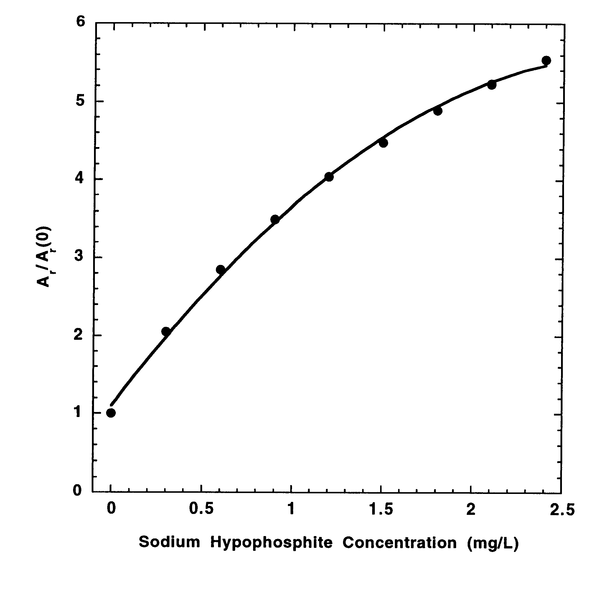
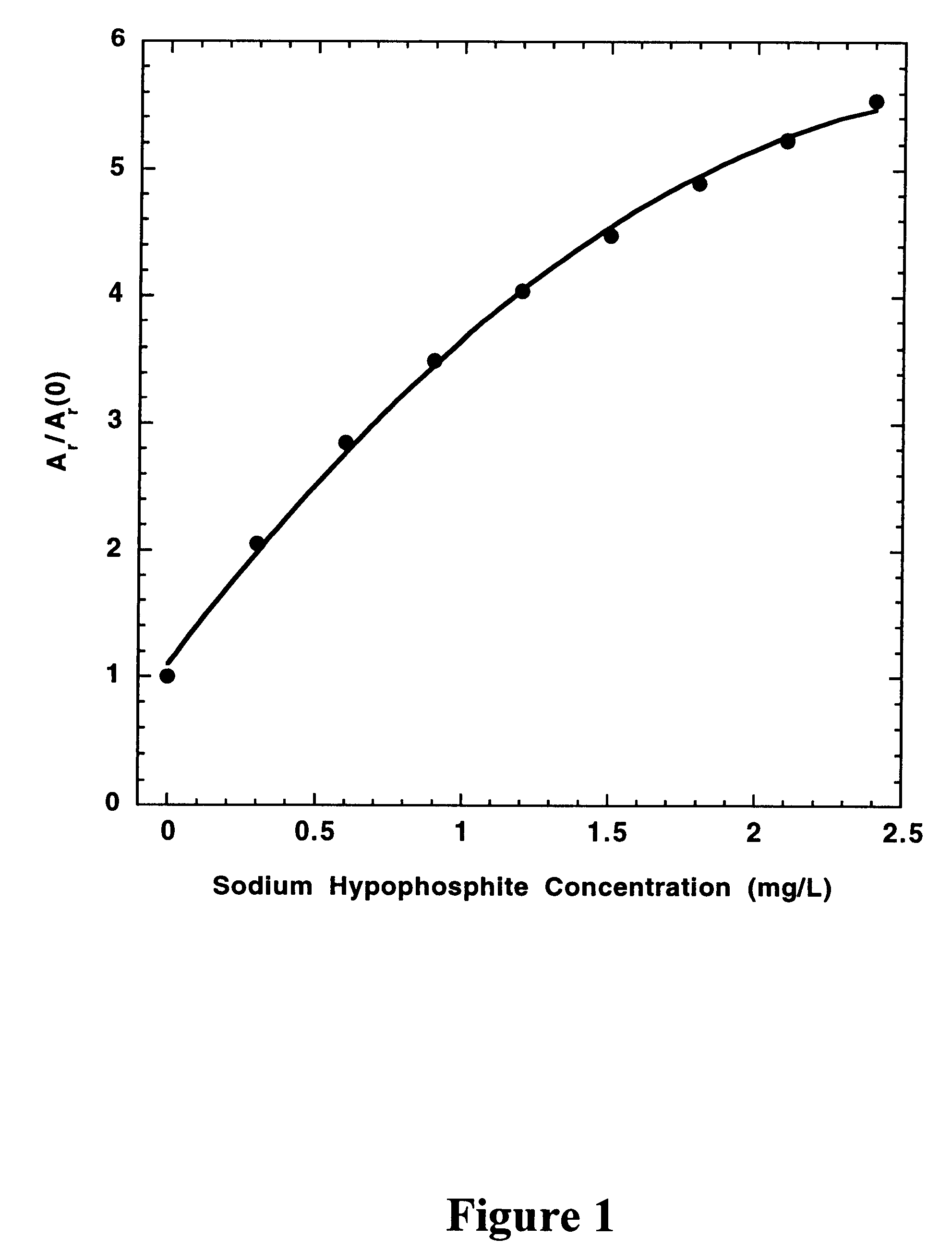
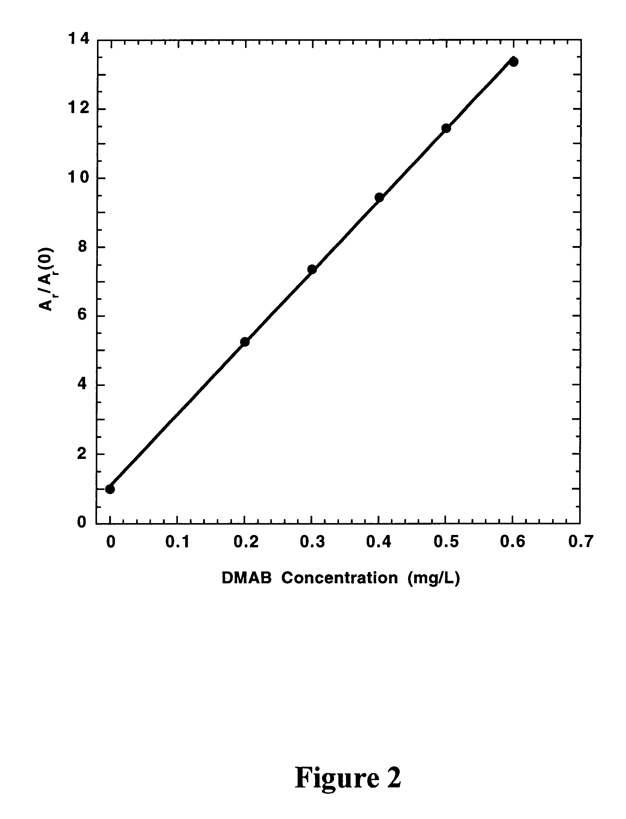
In a preferred embodiment of the present invention, the concentrations of hypophosphite and dimethylamineborane (DMAB) reducing agents in electroless cobalt and nickel plating baths are determined from the effects of standard additions of the electroless plating bath and the reducing agents on the CVS stripping peak area (A.sub.r) measured at a rotating Pt disk electrode in an acid copper sulfate electrodeposition solution. For A.sub.r measurements, the electrode potential is either cycled at a constant rate between fixed positive and negative limits, or is biased at a fixed negative potential and then scanned in the positive direction at a constant rate to strip copper deposited during a predetermined time at the fixed negative potential. The negative voltage limit or the fixed negative potential is preferably predetermined to be just positive of the potential at which copper is electrodeposited at a substantial rate in the absence of reducing agent additions to the electrodepositi...


PUM

PropertyMeasurementUnit
diameteraaaaaaaaaa
diameteraaaaaaaaaa
temperatureaaaaaaaaaa

Abstract

The concentration of a reducing agent in an electroless bath for plating a first metal is determined from the effect of the reducing agent on the electrodeposition rate of a second metal. For electroless cobalt and nickel baths, a sample of the electroless plating bath is added to an acid copper plating solution and the copper electrodeposition rate is measured by cyclic voltammetric stripping (CVS) analysis. Separate analyses for hypophosphite and dimethylamineborane in baths employing both reducing agents are attained via selective decomposition of the dimethylamineborane in acidic solution.

Description

1. Field of the InventionThis invention is concerned with analysis of reducing agents in electroless plating baths as a means of providing control over the deposit properties.2. Description of the Related ArtPlating baths are widely used by the electronics industry to deposit a variety of metals (copper, nickel and gold, for example) on various parts, including circuit boards, semiconductor chips, and device packages. Both electroplating baths and electroless plating baths are employed. For electroplating, the part and a counter electrode are brought into contact with the electroplating bath containing ions of an electrodepositable metal, and the metal is electrodeposited by applying a negative potential to the part relative to the counter electrode. For electroless plating, the bath also contains a reducing agent which, in the presence of a catalyst, chemically reduces the metal ions to form a deposit of the metal. Since the deposited metal itself may serve as the catalyst, the ele...

Claims


Application Information

Patent Timeline
Patent Type & Authority Patents(United States)
IPC IPC(8): C25D21/12G01N27/26C23C18/16G01N27/42
CPCG01N27/42C23C18/1617
Inventor PAVLOV, MICHAELCHALYT, GENEBRATIN, PETERKOGAN, ALEXPERPICH, MICHAEL JAMES
Owner ECI TECH
Why Eureka
Try Eureka