Gain linearizer for variable gain amplifiers

a variable gain amplifier and gain linearizer technology, applied in the field of communication circuits, can solve the problems of imposing a difficult specification on the required transmit power control range, degraded performance, and more difficult or difficult to accurately set the transmit output power to a particular level

Inactive Publication Date: 2004-03-23
QUALCOMM INC
View PDF14 Cites 51 Cited by
  • Summary
  • Abstract
  • Description
  • Claims
  • Application Information

AI Technical Summary

Problems solved by technology

Thus, the transmitted signal from each transmitting user acts as interference to those of other users in the system.
These phenomena, in combination with the need to control the transmit power, can impose a difficult specification on the required transmit power control range.
VGAs having transfer functions that are not linear in dB can cause degraded performance.
For example, a "distorted" (i.e., not linear) transfer function can make it more difficult or challenging to accurately set the transmit output power to a particular level.
In CDMA systems, this inaccuracy can result in degraded performance for a particular remote station (if the output power is set too low) or lower system capacity (if the output power is set too high).
For example, a non-linear gain versus control voltage can lead to large gain slopes, which allow noise to more easily transfer onto the transmitted signal.
The large gain slopes can also disturb the stability of the AGC loop.

Method used


Image

  • Gain linearizer for variable gain amplifiers
  • Gain linearizer for variable gain amplifiers
  • Gain linearizer for variable gain amplifiers

Examples


Embodiment Construction

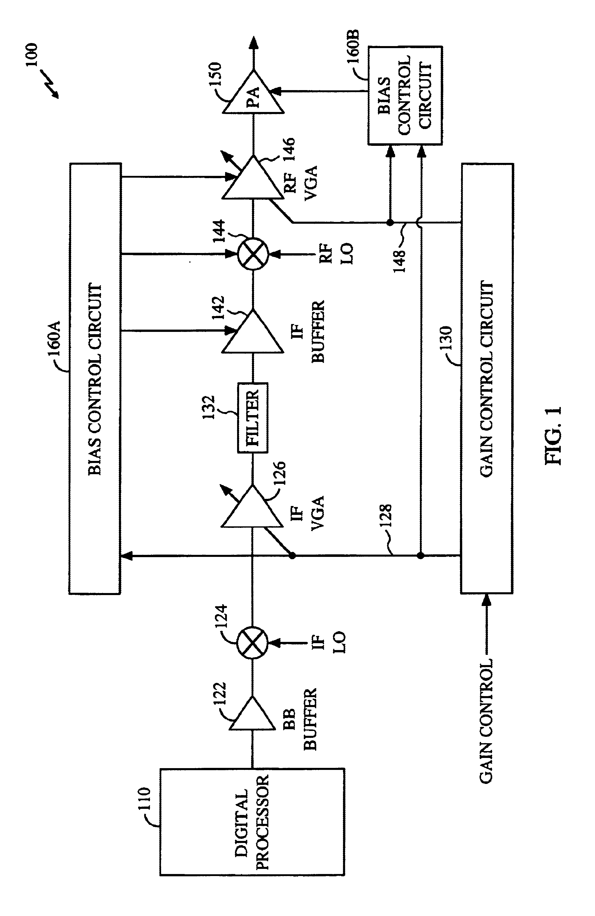
FIG. 1 shows a simplified block diagram of an embodiment of a transmitter 100. A digital processor 110 generates data, encodes and modulates the data, and converts the digitally processed data into an analog signal. The analog signal is provided to a baseband (BB) buffer 122 that buffers the signal and provides the buffered signal to a mixer 124. Mixer 124 also receives a local sinusoid at an intermediate frequency (IF LO), and upconverts the buffered baseband signal with the IF LO to generate an IF signal. The IF signal is provided to an IF variable gain amplifier (IF VGA) 126 that amplifies the signal with a gain determined by a gain control signal 128 from a gain control circuit 130. The amplified IF signal is provided to a filter 132 that filters the IF signal to remove out-of-band noise and undesired signals.

The filtered IF signal is provided to an IF buffer 142 that buffers the signal and provides the buffered IF signal to a mixer 144. Mixer 144 also receives a local sinusoid ...


PUM


Abstract

Techniques to linearly (in dB) adjust the gains of variable gain elements (i.e., variable gain amplifiers or VGAs) in a receiver or transmitter. An input control signal is provided to a conditioning circuit that conditions the control signal to achieve various signal characteristics. The input control signal is limited to within a particular range of values, temperature compensated, scaled (or normalized) to the supply voltages, shifted with an offset, or manipulated in other fashions. The conditioned signal is then provided to an input stage of a linearizer that generates a set of exponentially related signals. This is achieved using, for example, a differential amplifier in which the conditioned control signal is applied to the inputs of the differential amplifier and the collector currents from the differential amplifier comprises the exponentially related signals. An output stage within the linearizer receives the exponentially related signals and, in response, generates a gain control signal. By approximately matching the output stage to a gain stage of the variable gain element and by using the gain control signal generated by output stage, the gain transfer function of the VGA approximates that of the exponentially related signals.

Description

I. Field of the InventionThe present invention relates to communications circuits. More particularly, the present invention relates to novel and improved techniques for adjusting the gain of variable gain amplifiers.II. Description of the Related ArtVariable gain amplifiers (VGAs) are commonly used in communications receivers and transmitters to provide adjustable gain, and thus variable signal amplitude, depending on, for example, operating conditions, system requirements, or other factors. In particular, some transmitters are required to provide a range of adjustment in their output power. One application that requires this power adjustment is a Code Division Multiple Access (CDMA) communications system.In the CDMA system, the signal from each user is spectrally spread over the entire (e.g., 1.2288 MHz) system bandwidth. Thus, the transmitted signal from each transmitting user acts as interference to those of other users in the system. To increase system capacity, the output power...

Claims


Application Information

Patent Timeline
Patent Type & Authority Patents(United States)
IPC IPC(8): H03G7/00H03G7/08H03G3/10H03G7/06H03G3/30
CPCH03G7/08H03G3/00
Inventor WALKER, BRETT C.ZEISEL, ERICSAHOTA, GURKANWAL S.
Owner QUALCOMM INC
Why Eureka
Try Eureka