Carbon nanotube flow sensor device and method

a flow sensor and carbon nanotube technology, applied in the direction of fluid speed measurement, measurement devices, instruments, etc., can solve the problems of method dependent, limited application of this method, and large equipment requirements (lasers, ccd cameras) to achieve the effect of accurate measurement and low response tim

Inactive Publication Date: 2004-04-13
INDIAN INSTITUTE OF SCIENCE
View PDF7 Cites 23 Cited by
  • Summary
  • Abstract
  • Description
  • Claims
  • Application Information

AI Technical Summary

Benefits of technology

The main object of the invention is to provide a flow sensor which is operable even at very low flow velocities of 10.sup.-8 m / s with accuracy in measurement and low response times of 0.01 seconds.
In yet another embodiment of the invention, the conducting elements of the energy conversion means is provided with a protective insulating coating to prevent electrical contact with the liquid, thereby ensuring that accidental discharge of electricity generated due to liquid flow along the surface thereof to the liquid does not occur.

Problems solved by technology

However, this method has several disadvantages.
The primary disadvantage is the underlying assumption that the movement of all the colloidal particles assume the direction of the flow.
Thus, the application of this method is limited to velocities of greater than 0.02 m / s.
The equipment required (lasers, CCD cameras) is also large in size.
Another disadvantage is that the method is dependant entirely on image analysis and thereby on the analysis algorithms.
Since the particle imaging velocimetry method measures the velocity of the colloidal particles and there is no direct digital signal corresponding to the liquid velocity, the flow velocity of pure liquid cannot be measured.
The method also is not appropriate for systems where optical access is absent and for liquids that are turbid.
However, this method also suffers from several disadvantages.
This method also requires large and expensive equipment such as a plurality of lasers and digital counters.
Another significant disadvantage of this method is that it is restricted to a single point measurement with the data obtained being completely dependant on the particle arrival in the measuring volume and not on user requirements.
This method also does not work in systems where optical access to the liquid flow path at the measurement volume is absent.
As a result while the Mie scattering intensity is substantially better in the forward direction, it is difficult to set up forward receiving optics which remain aligned to the moving measurement volume.
Greater noise at higher speed with radio frequency interference is possible.
However, in this method a slight variation in the temperature, pressure or composition of the fluid under study can result in erroneous readings.
In addition, even such compensating electronics can be subject to error.
At low velocities, the convection currents in the liquid cause a malfunction in the sensor.
Thus while useful for small flow rates, the device is not appropriate for liquids with high viscosity.
However, while this device is operable at flow rates of the rate of a few .mu.L / s, the volumetric flow rates and not flow velocities are measured.
The equipment size is also large rendering it expensive.
Thus it is not suitable for biological systems which involve small volumes of liquid flowing at low flow velocity.
However, this device suffers from several limitations such as the inability to distinguish between forward, reverse and cross flow.
Another disadvantage of this flow sensor is that a plurality of wires are required, for example for carrying the output voltage to the pacemaker and another pair to heat the flow sensor.
However, the problem of an external power source to heat the thermopile is not avoided.
The construction of this device is also quite complex and expensive.
Nuclear power plants require expensive safety equipment and measures in view of the potential for radiation leakage.
Thermal power plants use fossil fuels which result in the attendant problems of pollution and also suffer from reduced supplies due to depletion of fossil fuels and oil.
The equipment required is also expensive and occupies a large area.
However, the magnitude of the power generated in relation to the size of the device renders it unsuitable for use for large scale energy conversion.

Method used


Image

  • Carbon nanotube flow sensor device and method
  • Carbon nanotube flow sensor device and method
  • Carbon nanotube flow sensor device and method

Examples


example 2

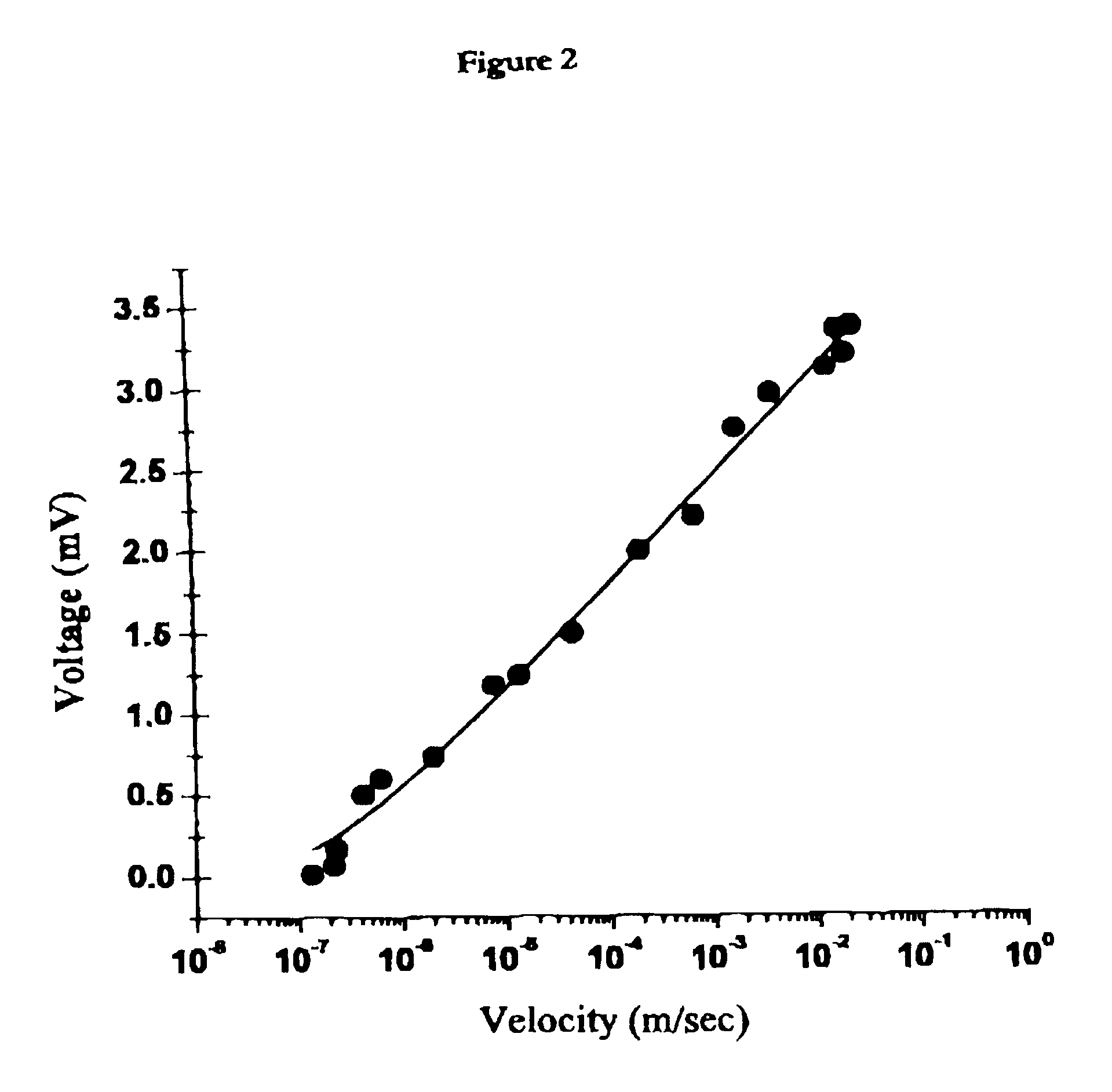
In order to determine the relation between the voltage generated and the liquid viscosity .eta., the experimental set up of Example 1 was repeated with different liquids. The liquids used were a water--glycerol mixture of water glycerol=88:12 (.eta.=113 mPas) and water:glycerol=75.multidot.25 (.eta.=234 mPas). These mixtures have viscosity of about two orders of magnitude higher than that of water (.eta.=0.9 mPas). Other liquids tested comprised of methanol, 0.6M HCl and 1.2MHCl. The values obtained are given in FIG. 3. It was also observed that the voltage developed in the case of polar liquids such as water were higher than for non-polar liquids such as methanol. Thus for .mu.=6.times.10.sup.-4 m / s, V.sub.water =2.1 mV, whereas V.sub.methanol =0.2 mV. The data obtained confirmed that the voltage response to flow velocity is sublinear (nearly logarithmic), is also dependant on the sonic and polar nature of the liquid and is relatively weakly dependant on the viscosity of the liquid...

example 3

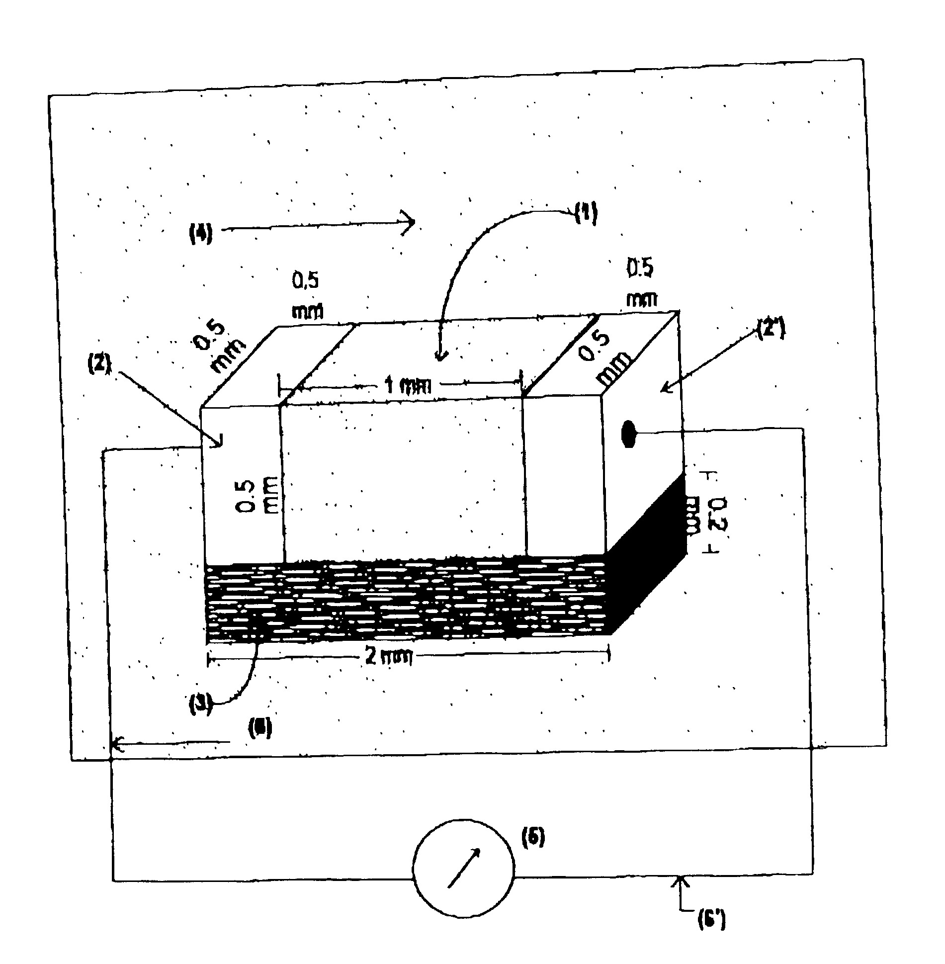
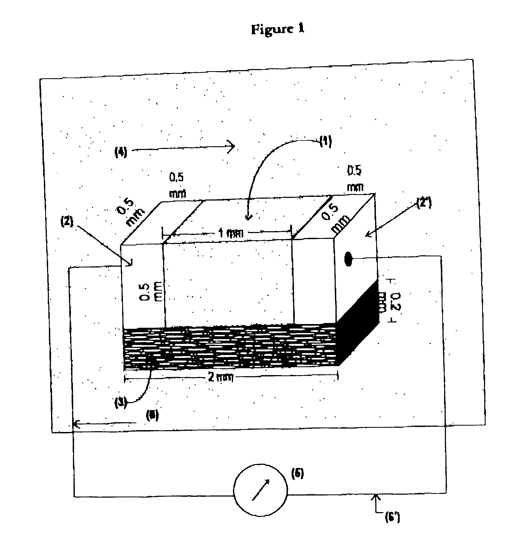
Single wall carbon nanotube bundles were prepared by electric arc method followed by purification. The nanotube bundles prepared had an average tube diameter of 1.5 nm and were densely packed between two metal electrodes. The dimensions of the sensor sample were 1.times.10.sup.-3 m along the flow, 2.times.10.sup.-4 m thickness and 2.times.10.sup.-3 m width. The resistivity of the sensor material was about 0.02 .OMEGA.-m, and the sensor has a linear current voltage characteristic of up to 20 mV.

When the sensor bundle was immersed in blood it was observed that voltage developed only along the direction of the flow and not perpendicular thereto. The measurement protocol was as given in Example 1 above. The measurements were taken at different flow velocities for blood. The velocity and corresponding voltage values obtained are given in Table 1 below and also represented in FIG. 5. The values an FIG. 5 fits the empirical relation of V=.alpha.log(.alpha..beta.+1) where .alpha.=0.6 mV and...


PUM


Abstract

A method and device for measuring the flow of a liquid utilizes at least one carbon nanotube. More particularly, the velocity of a liquid along the direction of the flow is measured as a function of the current / voltage generated in at least one carbon nanotube due to the flow of the liquid along its surface.

Description

The present invention relates to a carbon nanotube--based liquid flow sensing device. The present invention also relates to a method for measuring the flow of a liquid using carbon nanotube. More particularly, the present invention relates to a method for measuring the velocity of a liquid along the flow thereof as a function of the current / voltage generated in carbon nanotube due to the flow of the liquid along the surface thereof. In another application, the present invention also relates to a device for the conversion of energy comprising using at least one carbon nanotube and also to a method for the conversion of kinetic energy of a liquid flow into electrical energy using one or more carbon nanotubes.The measurement of liquid velocity along the direction of flow is of significant importance in several applications. For example, an accurate determination of velocity of ocean or river tides along the direction of the flow is important in predicting tidal patterns, potential weat...

Claims


Application Information

Patent Timeline
Patent Type & Authority Patents(United States)
IPC IPC(8): G01F1/56G01P5/08G01P5/00G01F1/64
CPCG01F1/56G01F1/64G01P5/08Y10S977/742Y10S977/953
Inventor SOOD, AJAY KUMARGHOSH, SHANKAR
Owner INDIAN INSTITUTE OF SCIENCE
Why Eureka
Try Eureka