Slip prevention particle injection device

a technology of injection device and injection chamber, which is applied in the field of slip prevention particle injection device, can solve the problems of low tacking coefficient between the wheels and the rails, high speed slippage of the wheels of railway rolling stock, and idle rotation of the wheels, so as to reduce the cost of preventing slippage, reduce production cost, and simple structure

Inactive Publication Date: 2004-04-20
RAILWAY TECH RES INST +1
View PDF24 Cites 9 Cited by
  • Summary
  • Abstract
  • Description
  • Claims
  • Application Information

AI Technical Summary

Benefits of technology

The injector device in accordance with the present invention has a simple structure. Therefore, the production cost is low. Moreover, si

Problems solved by technology

Rain or snow may cause slippage of wheels of railway rolling stock traveling at a high speed on rails.
Indeed, wetting of the rails with rain or accumulation of snow thereon causes such effects as the decrease in tacking coefficient between the wheels and the rails, idle rotation of the wheels, decrease in traveling speed, and inability to reach the preset traveling speed.
Furthermore, when brakes are applied to stop the railway rolling stock, it cannot be stopped in a predetermined stoppage position due to slippage of wheels and the stoppage time required to stop the railway rolling stock after the application of brakes is extended.
Since the sand sprinkling mechanism was based on the sand falling under gravity, the sand was scattered by the wind pressure created by the traveling railway rolling stock and the sand was difficult to sprinkle accurately at the appropriate location between the wheels and rails.
The drawback of all of the devices is in that the injected quantity of the particles is difficult to adjust.
However, the drawback of the conventional device is that the injected quantity is increased if the injection pressure is raised and the flow rate of compressed air is increased.
The excessive injection of particles causes unnecessary consumption of particles and the cost of slippage prevention rises.
Moreover, when the excessively sprinkled particles penetrate into a point gap, they make it impossible to operate the point or produce a negative effect on a signal circuit.
Another drawback of the conventional devices is that if the compressed air quantity is adjusted so that the injected quantity does not become too high, the prescribed injection pressure cannot be obtained and the particles cannot be accurately injected at the target location between the wheels and rails.
Thus, when an attempt was made to inject the particles accurately at the target location under the prescribed injection pressure, the injected quantity became too high.
On the other hand, when the compressed air quantity was adjusted so as to control the injected quantity to the appropriate level, the injection pressure was insufficient, the particles were not injected at th

Method used


Image

  • Slip prevention particle injection device
  • Slip prevention particle injection device
  • Slip prevention particle injection device

Examples


Embodiment Construction

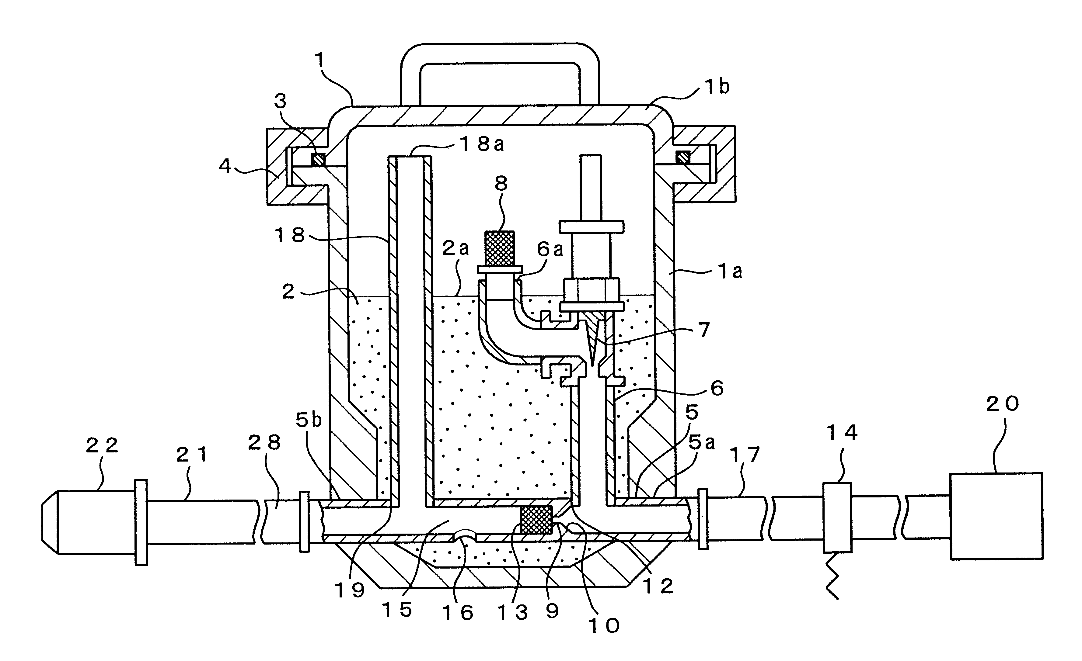
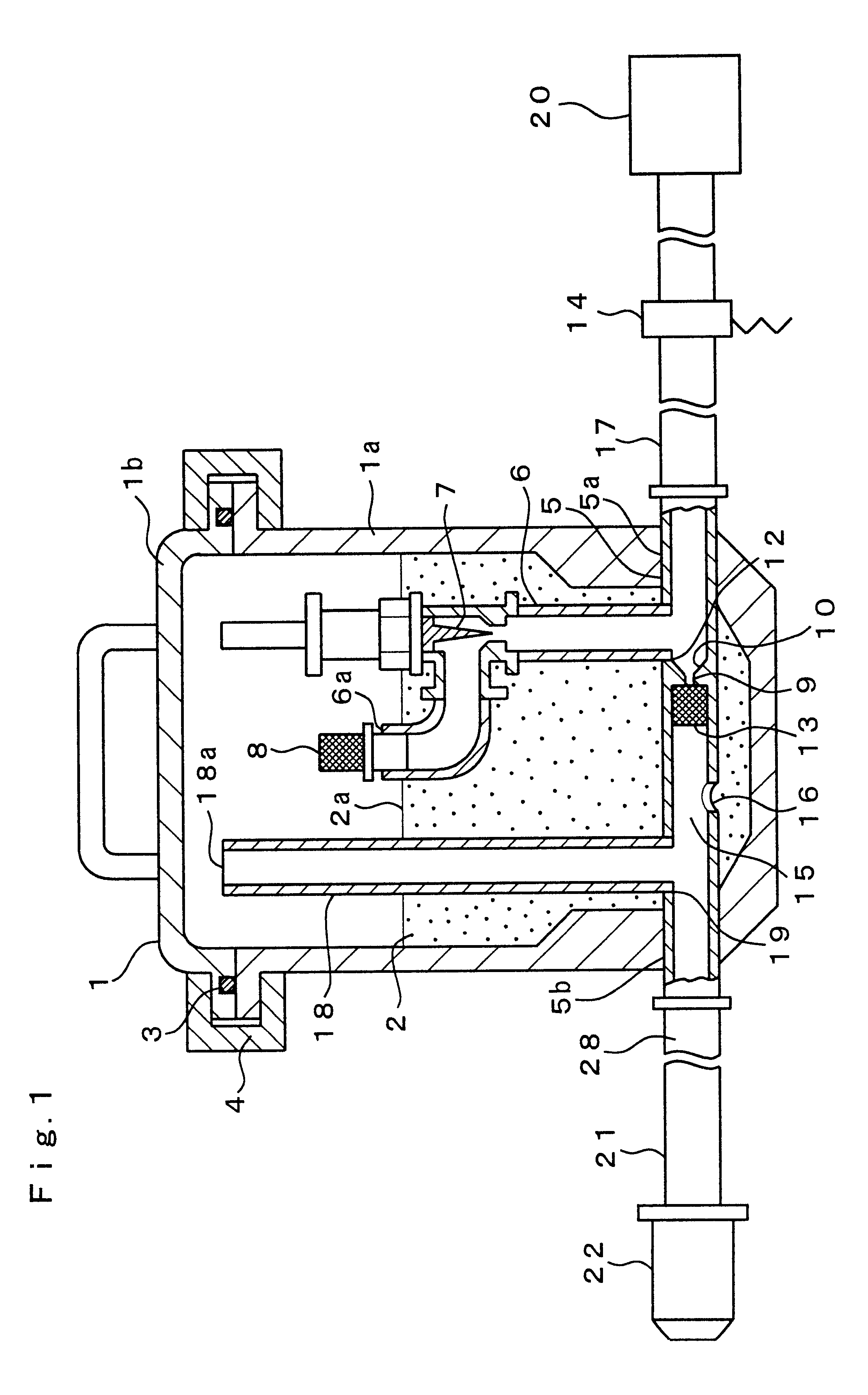
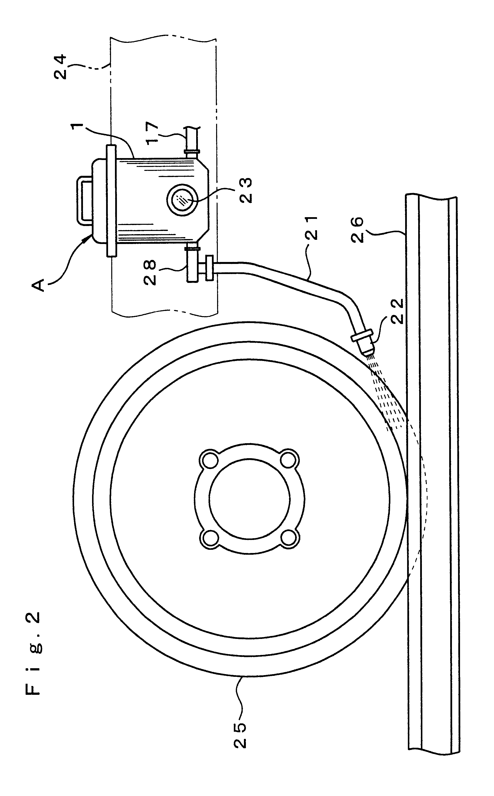
FIG. 1 illustrates an embodiment of the injector device in accordance with the present invention. In the figure, the reference numeral 1 stands for a particle retainer tank retaining slippage-preventing particles 2. The tank 1 comprises a tank body 1a and a cover 1b and is constructed as a pressure-resistant sealed container. The pressure resistance ability of tank 1 is preferably no less than 10 kgf / cm.sup.2. The tank 1 is opened via the cover 1b and the inside of the tank body 1a is filled with the prescribed quantity of slippage-preventing particles 2. In a closed state, air-tight contact between the tank body 1a and cover 1b is maintained by an O ring 3. Moreover, the cover 1b is tightly secured to the tank body 1a with a locking part 4.

Any particles increasing tacking coefficient between the wheels and rails may be used as the slippage-preventing particles 2. Examples of suitable particles include natural sand, silica sand, alumina particles, metal particles, or ceramic particl...


PUM


Abstract

Problems are posed by slip prevention particle injection devices by wheels of railway rolling stock. Namely, if the injected quantity of slippage-preventing particles is adjusted so as not to be excessive and to be a suitable quantity, it is not possible to obtain a predetermined injection pressure and it is not possible to inject the particles at the target location. The injector device of the present invention is constituted by providing an air through-flow duct 5 inside a particle retainer tank 1, and connecting an air supply duct 17 to this air through-flow duct 5. In the above mentioned tank 1, in addition to an air inflow duct 6 being provided in the vicinity of the inlet side of the air through-flow duct 5, an air discharge duct 18 is provided in the vicinity of the outlet side of the air through-flow duct 5. This air inflow duct 6 and air discharge duct 18 are connected to the air through-flow duct 5 and one end of these ducts 6 and 18 is open into the tank 1. Further, in addition to a mixing chamber 15 and a smaller-diameter air passage section 9 being provided in the air through-flow duct 5, a particle introduction hole 16 is provided in the mixing chamber 15, and an injector duct 21 that injects a fluid mixture of slippage-preventing particles and compressed air is provided at the outlet side of the air through-flow duct 5.

Description

TECHNICAL FIELDThe present invention relates to slip prevention particle injection devices which are installed in the vicinity of wheels of railway rolling stock and spread particles for preventing slippage of the wheels.BACKGROUND ARTRain or snow may cause slippage of wheels of railway rolling stock traveling at a high speed on rails. Indeed, wetting of the rails with rain or accumulation of snow thereon causes such effects as the decrease in tacking coefficient between the wheels and the rails, idle rotation of the wheels, decrease in traveling speed, and inability to reach the preset traveling speed. Furthermore, when brakes are applied to stop the railway rolling stock, it cannot be stopped in a predetermined stoppage position due to slippage of wheels and the stoppage time required to stop the railway rolling stock after the application of brakes is extended.In order to resolve those problems, sand has been sprinkled between the wheels and the rails to prevent the slippage of t...

Claims


Application Information

Patent Timeline
IPC IPC(8): B61C15/10B61C15/00
CPCB61C15/102
Inventor OHNO, KAORUMATSUOKA, KOSUKEWATANABE, KOUZOU
Owner RAILWAY TECH RES INST
Why Eureka
Try Eureka