Discharge light-emitting device and method manufacture thereof

a technology of discharge light and discharge tube, which is applied in the manufacture of electrode systems, electric discharge tubes/lamps, and luminescence, etc., can solve the problems of phosphor thermal degradation, and achieve the effects of reducing discharge voltage, reducing discharge voltage, and enhancing electron amplification action of water vapor

Inactive Publication Date: 2004-06-01
PANASONIC CORP
View PDF9 Cites 13 Cited by
  • Summary
  • Abstract
  • Description
  • Claims
  • Application Information

AI Technical Summary

Benefits of technology

With this construction, the water vapor in the gas medium delivers a function of amplifying electrons at the time of discharge. This makes it possible to reduce a voltage which is applied to display electrodes to cause discharge (discharge voltage). Which is to say, when colliding with electrons, the water vapor discharges electrons more easily than a discharge gas such as a noble gas. This electron discharge reaction tends to proceed in a cascade-like manner. As a result, electrons are amplified remarkably.
Also, there is conventionally no such idea that the discharge voltage can be reduced by controlling the amount of water vapor. On the other hand, this embodiment controls the water vapor partial pressure of the discharge gas to reduce the discharge voltage. This control can be done relatively easily. Since the heating is performed while supplying dry gas with a limited water vapor content during the sealing process, the amount of residual water vapor in the PDP after the sealing process is very low. In other words, there is a high degree of dryness in the PDP. Water vapor is introduced in such a dry state, so that the water vapor content of the discharge gas in the completed PDP can be adjusted without difficulty. In other words, since the dryness of the inside of the PDP enclosed.

Problems solved by technology

It is generally known that a phosphor suffers thermal degradation during the sealing process.

Method used


Image

  • Discharge light-emitting device and method manufacture thereof
  • Discharge light-emitting device and method manufacture thereof
  • Discharge light-emitting device and method manufacture thereof

Examples


first embodiment

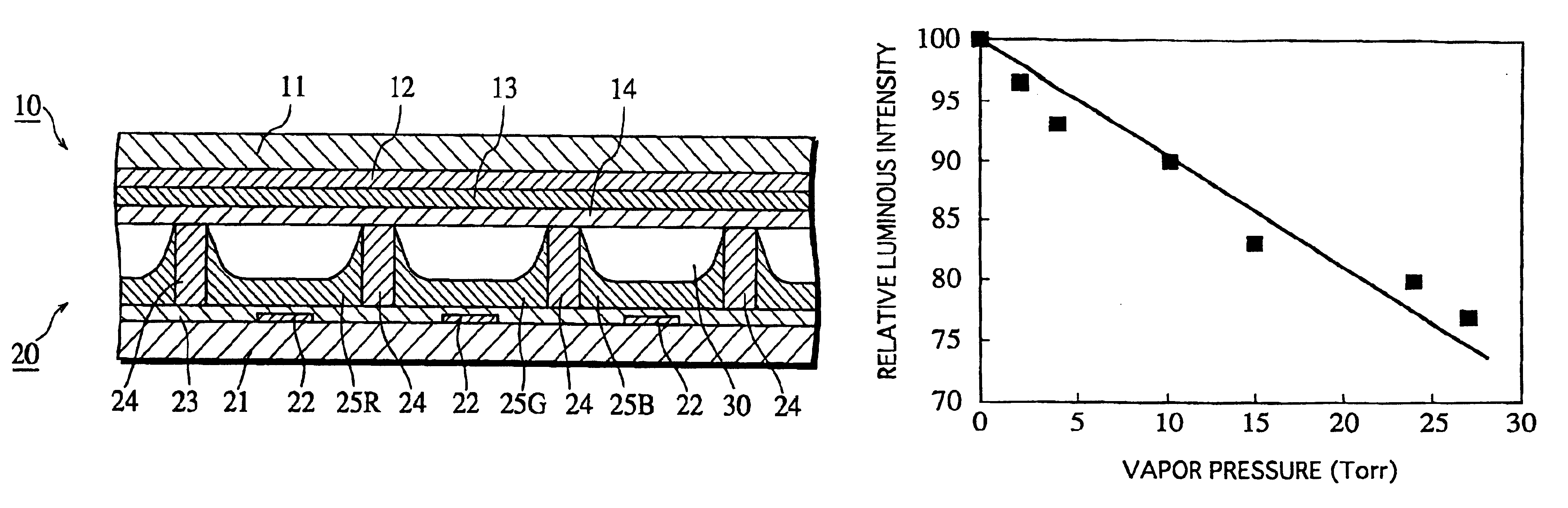
A plurality of panels were manufactured under different manufacturing conditions based on the first embodiment and the like. The characteristics of each panel are shown in TABLE 1.

Panels 1 to 5 correspond to the actual example and were manufactured based or the above embodiment In these panels, vapor-containing gas was introduced as discharge gas, with the water vapor content of the gas being varied for each panel. In panels 1 to 4, the sealing was performed with the panel inside being set in a dry atmosphere. In panel 5, the sealing was performed with the panel inside being set not in a dry atmosphere.

Panels 6 and 7 correspond to the comparative example. In panel 6, the sealing was performed with the panel inside being set in a dry atmosphere, and a conventional discharge gas with little water vapor (a gas mixture of Ne and Xe that contains little water vapor) was introduced. In panel 7, the sealing was performed with the panel inside being set not in a dry atmosphere, and a conven...

second embodiment

(Second Embodiment)

In the second embodiment, the sealing in the sealing process is performed while supplying dry gas such as air or noble gas whose water vapor partial pressure has been adjusted within 0.13 kPa (1 Torr), as in the first embodiment. In so doing, the thermal degradation of the phosphors in the sealing process can be avoided.

Also, instead of introducing water vapor in the discharge gas filling process, the manufacturing operation of this embodiment includes a process of introducing a gas medium such as air or noble gas that contains a predetermined amount of water vapor into the PDP between the sealing process and the evacuation process, in order to reduce the discharge voltage.

This process can be carried out using the following device. FIG. 6 is a plan view showing a construction of a manufacturing device used in this process.

First, the sealed PDP is placed in a heating furnace 101. Here, glass tubes 102a and 102b that also serve as exhaust tubes are provided to the b...

third embodiment

(Third Embodiment)

In the third embodiment, the sealing in the sealing process is performed while supplying dry gas such as air or noble gas whose water vapor partial pressure has been adjusted within 0.13 kPa (1 Torr), as in the above embodiments. In this way, the thermal degradation of the phosphors in the sealing process can be avoided.

Also, instead of introducing water vapor in the discharge gas filling process, the manufacturing operation of this embodiment includes a process of introducing, from halfway through the sealing process, a gas medium such as air or noble gas that contains a predetermined amount of water vapor into the PDP, in order to reduce the discharge voltage.

This process can be carried out using the following device. FIG. 8 is a plan view of a construction of a manufacturing device used in this process.

First, the front and back panels which have not been sealed yet are sandwiched together and placed in a heating furnace 111. Here, glass tubes 112a and 112b that ...


PUM


Abstract

A discharge light-emitting device includes a gas-filled discharge spaces (30) to use electric discharge in the gas. The gas contains at least 0.01-1% water vapor by volume. The specified amount of water vapor decreases discharge voltage markedly. Water vapor is introduced between a sealing step and an evacuation step so that the gas-filled discharge spaces can finally contain a desired amount of water vapor.

Description

The present invention relates to a gas discharge light-emitting device, such as a plasma display device, a noble-gas barrier discharge lamp, and an electrodeless discharge lamp, which is used for image display in computer monitors, televisions, and the like, and a manufacturing method for the gas discharge light-emitting device.FIG. 10 is a sectional view showing a construction of a panel part of a conventional AC (alternating current) plasma display device.In the drawing, reference numeral 201 denotes a front glass substrate. A plurality of pairs of display electrode lines 202 are formed in parallel with each other on the front glass substrate 201. A dielectric glass layer 203 is formed over the display electrode lines 202. A protective layer 204 made of magnesium oxide is formed on the dielectric glass layer 203.Reference numeral 211 denotes a back glass substrate. Address electrode lines 212 are formed on the back glass substrate 211. A visible light reflective layer 213 is forme...

Claims


Application Information

Patent Timeline
Patent Type & Authority Patents(United States)
IPC IPC(8): H01J17/49H01J17/02H01J17/20H01J9/26H01J11/50H01J9/38H01J9/395H01J11/38H01J11/42H01J61/16H01J61/30H01J65/04
CPCH01J9/261H01J9/395H01J11/12H01J11/48H01J11/50H01J61/16H01J61/305H01J65/04H01J11/38H01J11/42H01J9/38
Inventor KADO, HIROYUKIMIYASHITA, KANAKO
Owner PANASONIC CORP
Why Eureka
Try Eureka