
Polarizer and liquid crystal display element

a technology of liquid crystal display element and polarizer, which is applied in the direction of static indicating device, instruments, organic chemistry, etc., can solve the problems of insufficient polarization capability and low contrast, high cost and low thermostability of pva polarizers, and the inability to use them in mass-production consumer goods

Inactive Publication Date: 2004-07-27
GOSUDARSTVENNY NAUCHNY TSENTR ROSSIISKOI FEDERATSII NIOPIK GNTS RF NIOPIK +1
View PDF25 Cites 68 Cited by
  • Summary
  • Abstract
  • Description
  • Claims
  • Application Information

AI Technical Summary

Problems solved by technology

However, an high cost and a low thermostability of the polarizers based on PVA do not allow to use them in the mass-production consumer goods, in particular in manufacture of multi-layer glass and films for automotive industry, construction, architecture.
Among drawbacks of the polarizer according to U.S. Pat. No. 2,544,659 and Patent of Japan 1-183602 (A) should be mentioned, first of all, an insufficient polarizing capability and a low contrast.
But said polarizer has the polarization characteristics which are still insufficient for use in the high-resolution LC-devices.
When thickness of the layers is of the wavelength order, the light beams reflected from boundaries of the layers interfere with one another.
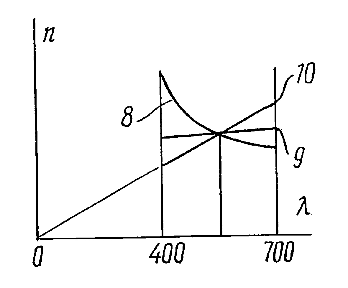
One of the disadvantages of the known polarizer is a comparatively strong spectral dependence of its optical characteristics, i.e. dependence of the polarizing capacity and the reflection (and transmittance) index on the polarizable light wavelength.
This disadvantage is caused by the circumstance that refraction indices in the used materials decrease as the polarized light wavelength increases.
The other disadvantage of the known polarizer according to Application PCT WO 95 / 17691 is the necessity to use a great number of the interleaving layers, which necessity is caused by the circumstance that the birefringence maximum value (difference between the ordinary and extraordinary refraction indices of a birefringent material) in transparent polymer materials is low and generally does not exceed 0.1-0.2.
For this reason the reflection index from the layer boundaries is small, and for the purpose to obtain an high reflection as the whole from an optical polarizer, it is necessary to use a great number (100-600) of layers, application of which layers is an extremely difficult task and requires special precision equipment.
Disadvantages of the polarizer according to U.S. Pat. No. 3,522,985 is a low efficiency of the outputted light polarization, caused by the following:
The major disadvantages of the polarizer according to U.S. Pat. No. 5,566,367, as well as those of the above-mentioned polarizers, is a relatively low polarization efficiency, a low degree of the outputted light polarization, and--in certain cases--a difficult manufacture thereof.
The polarizers presently used based on the polyvinyl alcohol films dyed with iodine vapours or dichroic dyes, have a low mechanical strength, and for this reason require special measures for protection against mechanical damages, which measures make LC-devices more complicated and expensive.
It should be noted that a damage to even one layers of a polarizer renders it unsuitable for manufacturing of a LCD element. see A. E. Perregaux, SPIE, Vol. 307, p.
a) A low thermal stability caused by use, for manufacture of such polarizer of polyvinyl alcohol or other vinyl polymers, and iodine--for dying;
b) Use for dyeing of polymer film of an iodine, which is soluble in LC, results an a lesser contrast and multiple rise of power consumption, which shortens the service life of such device.
An usual drawback of the devices of such type is a low brightness and an insufficient colour saturation of a produced image.
To attain an high colour saturation in this case a greater brightness of a light source is needed, which is connected with an increased energy consumption by a display.
An increased energy consumption results in losses of the LC displays' advantages as the energy-saving devices as compared with alternative devices for displaying information.
Metallic coatings are sufficiently simply applied, for example, by thermal evaporation in vacuum, but thereby in such coatings, absorption of light takes place, which diminishes transmission (reflection) of a polarizer.
In case of multi-layer dielectric mirrors, there is no light absorption therein, but the process of their application is rather complex and arduous. TiO.sub.2, MgO, ZnS, ZnSe, ZrO.sub.2, cryolite and polymers as the materials having an high refraction index can be used for these coatings, and as the materials having a low refraction index the following can be used: SiO.sub.2, Al.sub.2 O.sub.3 CaF.sub.2, BaF.sub.2 MgF.sub.2 AlN, BN, or polymers.
The presence of the low-motion organic ions in the polarizing coatings of the claimed optical polarizer results in a low conductivity, which in its turn lowers the energy consumption and thereby prolongs service life of the liquid-crystal devices.
Further, the presence of low-motion organic ions in polarizing coatings provides a low conductivity, which in its turn lowers the energy consumption, thus extending service life of liquid crystal devices.

Method used


Image

  • Polarizer and liquid crystal display element
  • Polarizer and liquid crystal display element
  • Polarizer and liquid crystal display element

Examples


Embodiment Construction

OF THE CLAIMED POLARIZER AND A LIQUID CRYSTAL DISPLAY ELEMENT

A Polarizer of the Interference Type

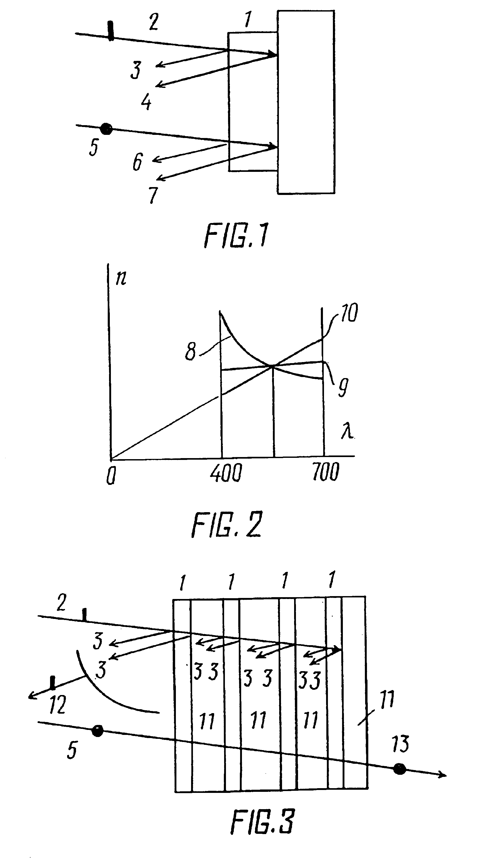
FIG. 1 shows a diagram of a one-layer polarizer of the reflecting type according to the invention, comprising birefringent anisotropically absorbing layer 1, said polarizer is characterized in that both its refraction indices (extraordinary n.sub.e and ordinary n.sub.o) are proportional to the polarized light wavelength. In the most simple version, layer 1 is adjacent from two sides to air. In more complex versions, on one of its surfaces applied is a light-reflecting coating. Layer 1 can be applied also on a substrate, and be, for example, of a transparent glass (shown in Fig. by phantom line).

Operation of the proposed polarizer of the reflecting type can be explained as follows. The non-polarized light consists of two linearly-polarized components 2 and 5, the polarization planes of which components are mutually perpendicular (these two components are conventionally separated in FIG. 1...


PUM

PropertyMeasurementUnit
angleaaaaaaaaaa
wavelengthesaaaaaaaaaa
temperatureaaaaaaaaaa

Abstract

The objective of the invention is to provide an highly efficient polarizer providing an improved brightness and color saturation of a LCI element based on such polarizer.This objective is to be attained by using, in manufacture of a polarizer and a LCI element based on such polarizer, at least one birefringent anisotropically absorbing layer having at least one refraction index that grows as the polarized light wavelength increases, i.e. having the abnormal dispersion.The use of said layer allows to create polarizers of both the dichroic and interference types. Further, the use of said layer allows to create a polarizer that provides, in a relatively simple design, conversion of practically all energy of a non-polarized radiation into the polarized radiation.The above-recited peculiarities of the claimed polarizer based on a birefringent anisotropically absorbing layer having the abnormal dispersion allow to create both a color and monochromic LCI element distinguished for an higher brightness, color saturation, good angular characteristics and absence of shadows.

Description

This invention relates to optics, and in particular to light polarizers and a liquid-crystal indicating elements based thereon.A light polarizer, that transforms the natural light into the polarized light, and a liquid-crystal display (LCD) element based thereon are of the necessary elements of the up-to-date devices for displaying information on liquid crystals (LC), monitoring systems and light blocking.DESCRIPTION OF THE PRIOR ARTThe polarizers presently used are polymer films oriented by the uniaxial stretching, and dyed in mass by organic dyes, or iodine compounds. As a polymer, polyvinyl alcohol (PVA) is mainly used. see, e.g. U.S. Pat. No. 5,007,942 (1991).Polarizers based on PVA dyed with iodine have high polarization characteristics and are widely used in production of liquid-crystal indicators for screens, watches, calculators, personal computers, etc.However, an high cost and a low thermostability of the polarizers based on PVA do not allow to use them in the mass-product...

Claims


Application Information

Patent Timeline
Patent Type & Authority Patents(United States)
IPC IPC(8): G02B3/00G02B5/04G02F1/1335G02B5/30G02F1/13
CPCG02B3/005G02B5/045G02B5/3033G02B5/3083G02F1/133528G02F1/133536G02B5/3025G02B3/0006G02B3/0031G02B3/0068Y10T428/1041Y10T428/10C09K2323/00C09K2323/031
Inventor MIROSHIN, ALEXANDR ALEXANDROVICHBELYAEV, SERGEI VASILIEVICHKHAN, IR GVONKARPOV, IGOR NIKOLAEVICHMALIMONENKO, NIKOLAI VLADIMIROVICHSHISHKINA, ELENA JURIEVNAVOROZHTSOV, GEORGY NIKOLAEVICH
Owner GOSUDARSTVENNY NAUCHNY TSENTR ROSSIISKOI FEDERATSII NIOPIK GNTS RF NIOPIK
Learn More