Plasma processing method and apparatus

a processing method and apparatus technology, applied in the field of plasma processing methods and apparatuses, can solve the problems of charging damage and adverse effect of electron amount on the charge oxide file of the gate oxide fil

Inactive Publication Date: 2004-08-17
HITACHI LTD
View PDF17 Cites 62 Cited by
  • Summary
  • Abstract
  • Description
  • Claims
  • Application Information

AI Technical Summary

Benefits of technology

It is an object of the present invention to provide a plasma processing method and apparatus which are configured to suppress the charging damage due to a device structure, thereby making it possible to process the surface with high precision.
According to an aspect of the invention, the method comprises the steps of carrying out the pulsed discharge by switching on and off the high frequency electric power for generating the plasma, controlling the off time of the pulsed discharge when the ratio of electron saturated current to ion saturated current (often referred to as the electron / ion saturated current ratio) is less than the predetermined value, controlling an inflow quantity of positive and negative charges to the sparse portion and the dense portion of the device patterns, and thereby suppressing the charging damage.
According to another aspect of the invention, the plasma processing apparatus is arranged to control an off time by switching on and off the high frequency electric power for generating the plasma to be charged, controlling the ratio of positive charges to negative charges to be flown into the sparse portion and the dense portion of the device patterns, and suppressing the voltage generated on a gate oxide film, thereby suppressing occurrence of the charging damage. This makes it possible to perform the highly accurate etching treatment.

Problems solved by technology

This phenomenon brings about a shortcoming that a potential difference is caused between an open area and a line and space area and thereby the gate oxide file is charging-damaged.
However, the experiment performed by the inventors of the present application indicated that the charging damage may have an adverse effect on the amounts of electrons and ions flown into the sparse portion with no pattern.

Method used


Image

  • Plasma processing method and apparatus
  • Plasma processing method and apparatus
  • Plasma processing method and apparatus

Examples


first embodiment

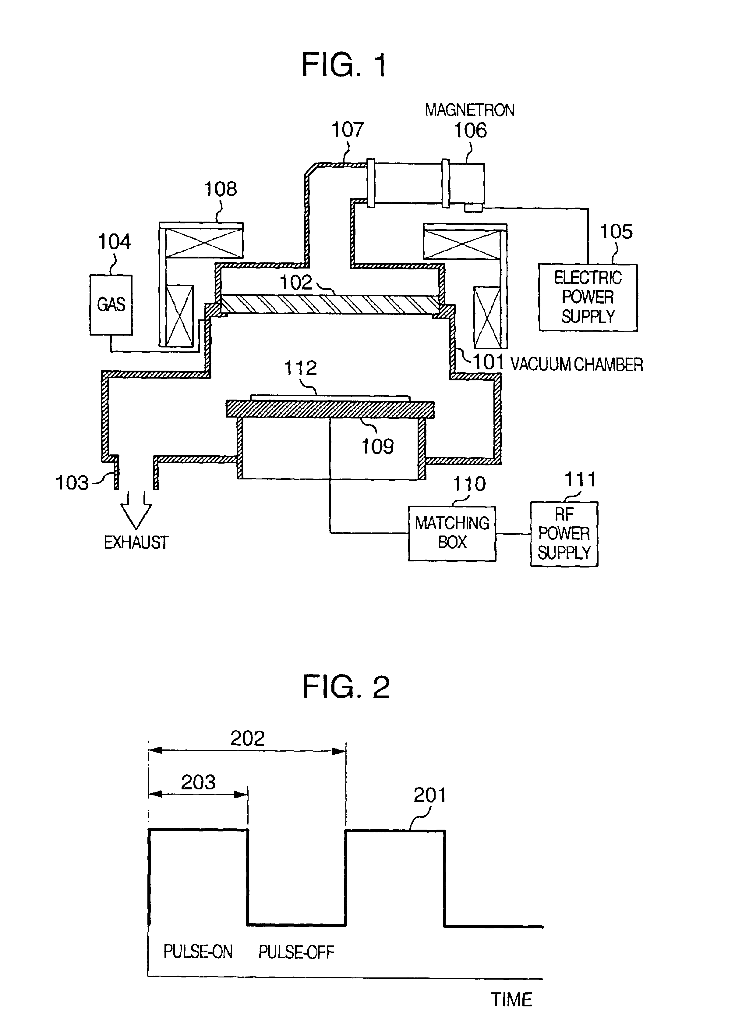
Hereafter, the present invention will be described with reference to FIGS. 1 to 7. FIG. 1 shows a microwave plasma etching apparatus that is an embodiment of the present invention. A numeral 101 denotes a vacuum chamber the top of which is opened. On the top of the vacuum chamber 101 is placed a dielectric window 102 (such as a quartz window) and then the chamber is sealed. The bottom of the vacuum chamber 101 is connected to a vacuum exhaust device (not shown) through a vacuum exhaust port 103. The upper portion of the vacuum chamber 101 is connected to a gas supply 104. The upper portion of the vacuum chamber 101 is connected to a waveguide 107 and a magnetron 106 through the dielectric window 102. The magnetron 106 is connected to an electric power supply 105 composing a high frequency power supply for generating a plasma together with the magnetron. The electric power supply 105 operates to switch on and off a microwave output at any frequency and any duty ratio. The upper perip...

second embodiment

[Second Embodiment]

The second embodiment of the present invention will be described with reference to FIG. 8. In this figure, the same numerals as those of FIG. 1 denote the same members about which description will be left out. The different respect of FIG. 8 from that of FIG. 1 will be described below. The upper portion of the vacuum chamber 101 is sealed by a dielectric window 801 (made of quartz, for example) and an upper electrode 802 (made of Si, for example). The upper electrode 802 has a porous structure from which etching gas is flown and is connected to gas supply device 104. The high frequency electric power such as 450 MHz power oscillated by an electric power supply 806 is transmitted to a tuner 804 through a high-pass filter 805. The high frequency electric power such as 13.56 MHz power oscillated by an antenna bias power supply 808 is also transmitted to the tuner 804 through a low-pass filter 807. These high frequency powers are then propagated to the inside of the v...

third embodiment

[Third Embodiment]

The third embodiment of the present invention will be described with reference to FIG. 9. In FIG. 9, the same numerals as those of FIG. 1 denote the same members. The different respect of FIG. 9 from that of FIG. 1 will be described below. The upper portion of the vacuum chamber 101 is sealed by the dielectric window 801 (made of quartz, for example) and the upper electrode 802 (made of Si, for example). The upper electrode 802 has a porous structure from which the etching gas is to be flown and is connected to the gas supply device 104. A high frequency electric power of, for example, 27 MHz or 60 MHz, oscillated by the electric power supply 903 serving as a high frequency power supply for generating the plasma is propagated to the inside of the vacuum chamber 101 through the upper electrode 802 in which chamber 101 the plasma is generated. The electric power supply 903 may be served to oscillate the modulated pulse. On the other hand, the substrate electrode 109 ...


PUM

PropertyMeasurementUnit
frequencyaaaaaaaaaa
frequencyaaaaaaaaaa
frequencyaaaaaaaaaa

Abstract

A plasma processing method and apparatus are provided for processing the surface of a semiconductor device or the like through the effect of plasma. A pulsed plasma discharge is performed by switching on and off the high frequency electric power for generating the plasma with a specified off period of the plasma generation, to control an inflow amount of positive and negative charges to sparse and dense portions of device patterns and suppress an electric potential on a gate oxide film. Thereby, a highly accurate etching process with no charging damage can be carried out.

Description

1. Field of the InventionThe present invention relates to a plasma processing method and apparatus, and more particularly to the plasma processing method and apparatus which are suited to treat the surface of an element like a semiconductor element through the effect of the plasma.2. Description of the Related ArtAs a technology of processing the surface of a substrate of a semiconductor element of the line through the effect of the plasma, as disclosed in Samakawa U.S. Pat. No. 5,827,435, there has been known a plasma processing method which is arranged to take the steps of generating positive ions in sufficient density by discharging the ECR plasma for about 10 .mu.sec, stopping the discharge for 100 .mu.sec for generating a massive number of positive and negative ions, at the same time, applying a RF electric field of 600 kHz into the ions only when the discharge is turned off, and charging only the positive and negative ions having the same mobility onto the substrate for suppre...

Claims


Application Information

Patent Timeline
Patent Type & Authority Patents(United States)
IPC IPC(8): C23C16/50C23C16/515H01J37/32
CPCC23C16/515H01J37/32192
Inventor SUMIYA, MASAHIROTAMURA, HITOSHIWATANABE, SEIICHI
Owner HITACHI LTD
Why Eureka
Try Eureka