

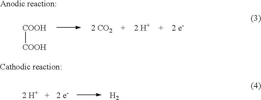
Electrochemical generation of carbon dioxide and hydrogen from organic acids
a technology of organic acids and carbon dioxide, applied in the field of electric generation of carbon dioxide and hydrogen from organic acids, can solve the problems of inconvenient stopping, difficult control of reaction, and inaccurate fluid delivery devices, and achieve the effect of constant rate of co2 and h2 generation and dissolution ra
- Summary
- Abstract
- Description
- Claims
- Application Information
AI Technical Summary
Benefits of technology
Problems solved by technology
Method used
Image

Examples
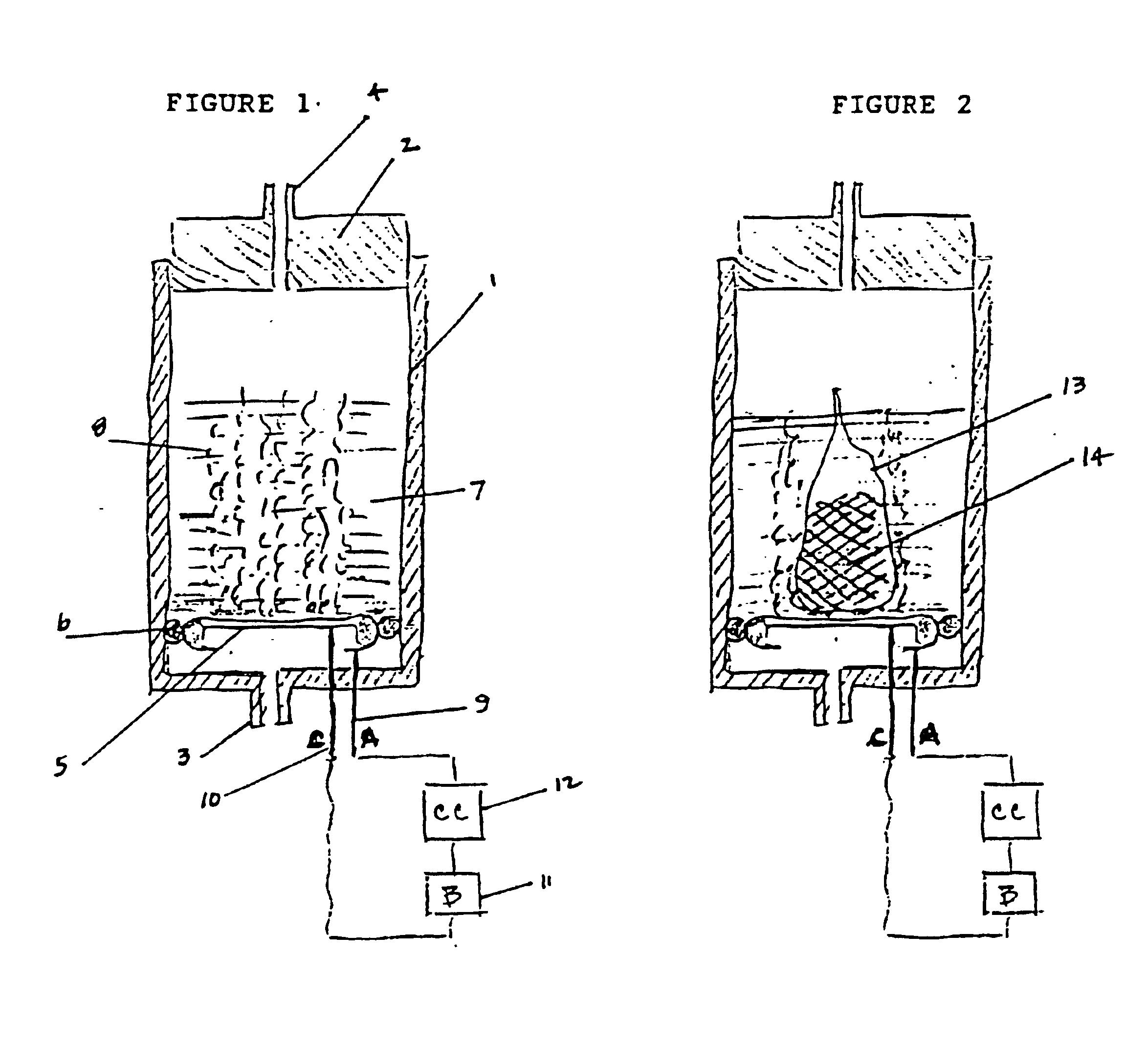
example ii
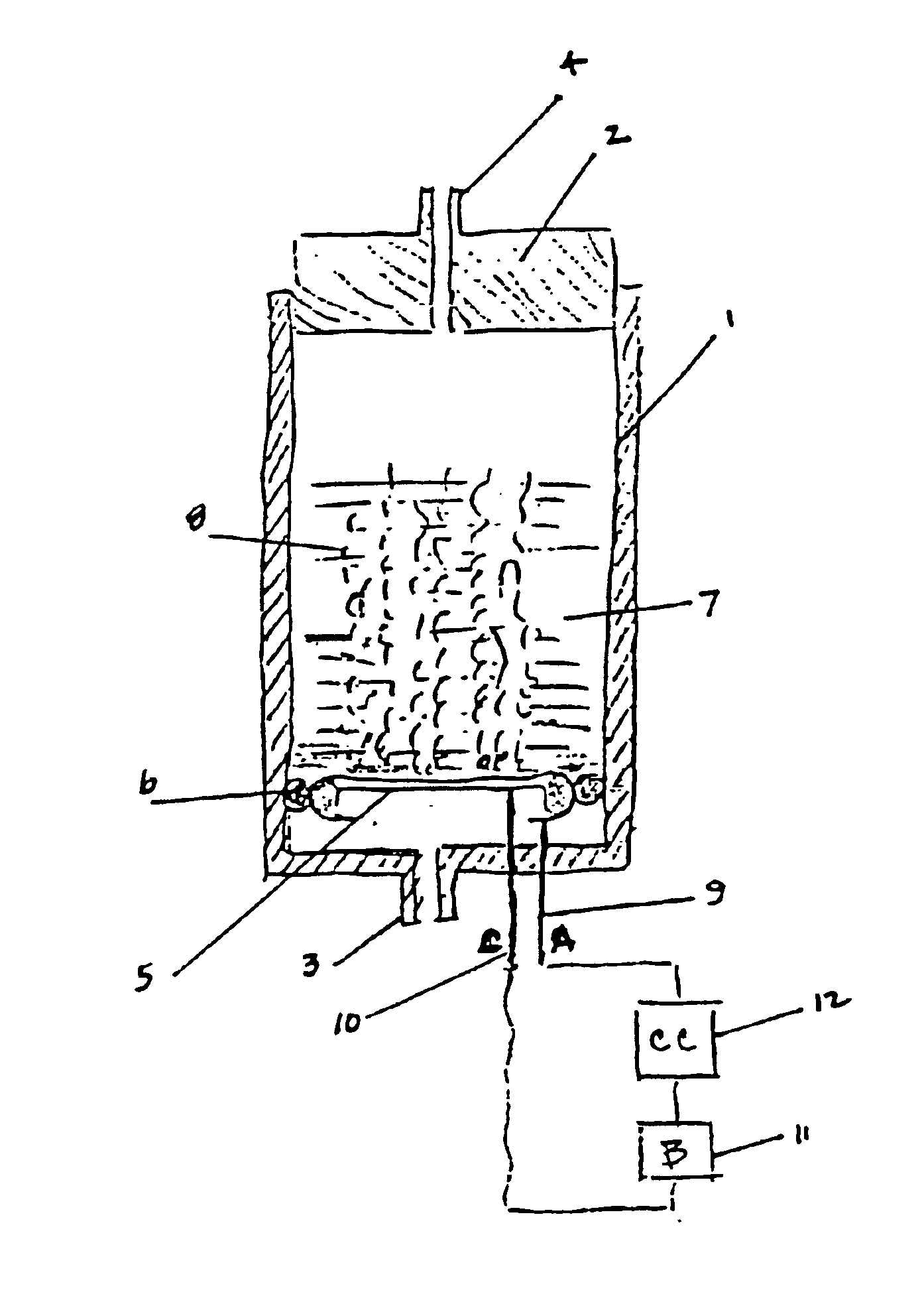
6.8 grams of oxalic acid, stored in a porous bag, are placed in 13.2 mL of deionized water. The current applied to the electrochemical cell is constant at 40 mA. The generator is operated continuously over a period of 87 hours. The average rate of gas generated at the anode is 33.8 cc / hr. The average rate of gas generated at the cathode is 16.6 cc / hr.
The gas composition of both anodic and cathodic streams is:
example iii
A saturated solution of oxalic acid in deionized water was electrochemically decomposed by applying a battery voltage supplied by two series-connected alkaline AA batteries. By manually changing the resistance from a variable resistor box, it was possible to change the current and voltage applied to the electrochemical cell. The following results were observed:
PUM
| Property | Measurement | Unit |
|---|---|---|
| current | aaaaa | aaaaa |
| current | aaaaa | aaaaa |
| energy | aaaaa | aaaaa |
Abstract
Description
Claims
Application Information