Thin permanent-magnet film and process for producing the same

a technology of permanent magnet and film, applied in the field of thin film permanent magnet, can solve the problems of difficult to improve both the magnetization and coercive force simultaneously, the thin film permanent magnet has not been put into practical use, and the improvement of both the magnetization and coercive force is difficult. , to achieve the effect of improving the residual magnetic flux density b.sub.r, increasing the magnetic anisotropy, and improving the coercive for

Inactive Publication Date: 2004-10-19
SUMITOMO SPECIAL METAL CO LTD
View PDF16 Cites 7 Cited by
  • Summary
  • Abstract
  • Description
  • Claims
  • Application Information

AI Technical Summary

Benefits of technology

In terms of the improvement in magnetic anisotropy of rare earth alloy magnetic layers, the material of refractory metal layers should not be arbitrarily selected, but it is necessary that the refractory metal layers are formed from at least one kind of material selected from a group consisting of Ti, V, Cr, Zr, Nb, Mo, Hf, Ta, and W. The R.sub.2 Fe.sub.14 B compound in the rare earth alloy magnetic layer has a tendency that if the compound is in contact with a refractory metal layer formed from the above-mentioned material during a deposition step or an annealing step (heat treatment step), the axis of easy magnetization thereof is oriented in a direction perpendicular to a face of the substrate. In other words, the above-mentioned refractory metal layer has functions of increasing the magnetic anisotropy of the rare earth alloy magnetic layer and of improving the residual magnetic flux density B.sub.r perpendicular to a plane.
In addition, these refractory metal layers 4, 6, 8, and 10 separate the rare earth alloy in the thin film permanent magnet in a direction of film thickness, so as to suppress the crystal growth of the tetragonal R.sub.2 Fe.sub.14 B compound. As a result, in each of the rare earth alloy magnetic layers 3, 5, 7, 9, and 11, fine metallurgical microstructure is formed, and the coercive force is improved. FIG. 2 shows a cross-sectional configuration of a prior-art thin film permanent magnet in which a single rare earth alloy layer 12 is formed on a substrate 1. As is seen from FIGS. 1 and 2, the total thickness of the rare earth alloy magnetic layers 3, 5, 7, 9, and 11 in this embodiment is substantially equal to the thickness of the rare earth alloy magnetic layer 12 in FIG. 2. The respective rare earth alloy magnetic layers 3, 5, 7, 9, and 11 in FIG. 1 are separated by the provision of the refractory metal layers 4, 6, 8, and 10. As a result, in the rare earth alloy magnetic layers 3, 5, 7, 9, and 11, the crystal growth of the tetragonal R.sub.2 Fe.sub.14 B compound is suppressed, and the metallurgical structure is sufficiently fined. This significantly contributes to the increase in coercive force.
It is known that the coercive force depends on the metallurgical microstructure and the crystal grain diameter of the R.sub.2 Fe.sub.14 B compound. In order to improve the coercive force, it is desirable that magnetic domain walls be prevented from moving by fining the crystals. In the thin film permanent magnet according to the present invention, as described above, the rare earth alloy magnetic layers are separated by the refractory metal layers in the film thickness direction, so that the crystal growth of tetragonal R.sub.2 Fe.sub.14 B is limited by the thickness of each of the magnetic layers. Therefore, by adjusting the rare earth alloy magnetic layers, the crystal grain diameter of the R.sub.2 Fe.sub.14 B compound can be optimized, and the coercive force can be increased.
A rare earth metal or an alloy including a rare earth metal which constitutes the rare earth alloy magnetic layer is easily oxidized, so that the deposition process is desirably conducted in a high vacuum atmosphere or an inert gas atmosphere. In addition to sputtering, vacuum evaporation and laser ablation are listed as preferable thin film deposition methods. Chemical, physical, and metallographic properties of the deposited layers by these methods depend on various conditions in the deposition process. Since the R--Fe--B alloy easily becomes amorphous, it is necessary to control the substrate temperature in the deposition process so as to be in the above-mentioned range, or to crystallize the alloy by a heating process after the deposition process.

Problems solved by technology

On the other hand, for a thin film permanent magnet primarily including the tetragonal Nd.sub.2 Fe.sub.14 B compound, it is difficult to improve both of the magnetization and the coercive force simultaneously, so that the thin film permanent magnet has not been put into practical use yet.
In the case of the thin film permanent magnet, one of the reasons which make the improvement of both of the magnetization and the coercive force difficult is that the magnetic anisotropy of the Nd--Fe--B based magnet formed by thin film deposition technique is lower than that of a bulk-like permanent magnet manufactured by a method such as powder metallurgy, or other means.
It is considered, however, that the degree of technical perfection does not reach the level of the technology used for making anisotropic magnetic materials in the powder metallurgy.
This is one of the factors preventing the properties of a thin film permanent magnet from being improved.
Thus, the metallurgical microstructure of the rare earth alloy magnetic film is not sufficiently controlled.

Method used


Image

  • Thin permanent-magnet film and process for producing the same
  • Thin permanent-magnet film and process for producing the same
  • Thin permanent-magnet film and process for producing the same

Examples


embodiment 1

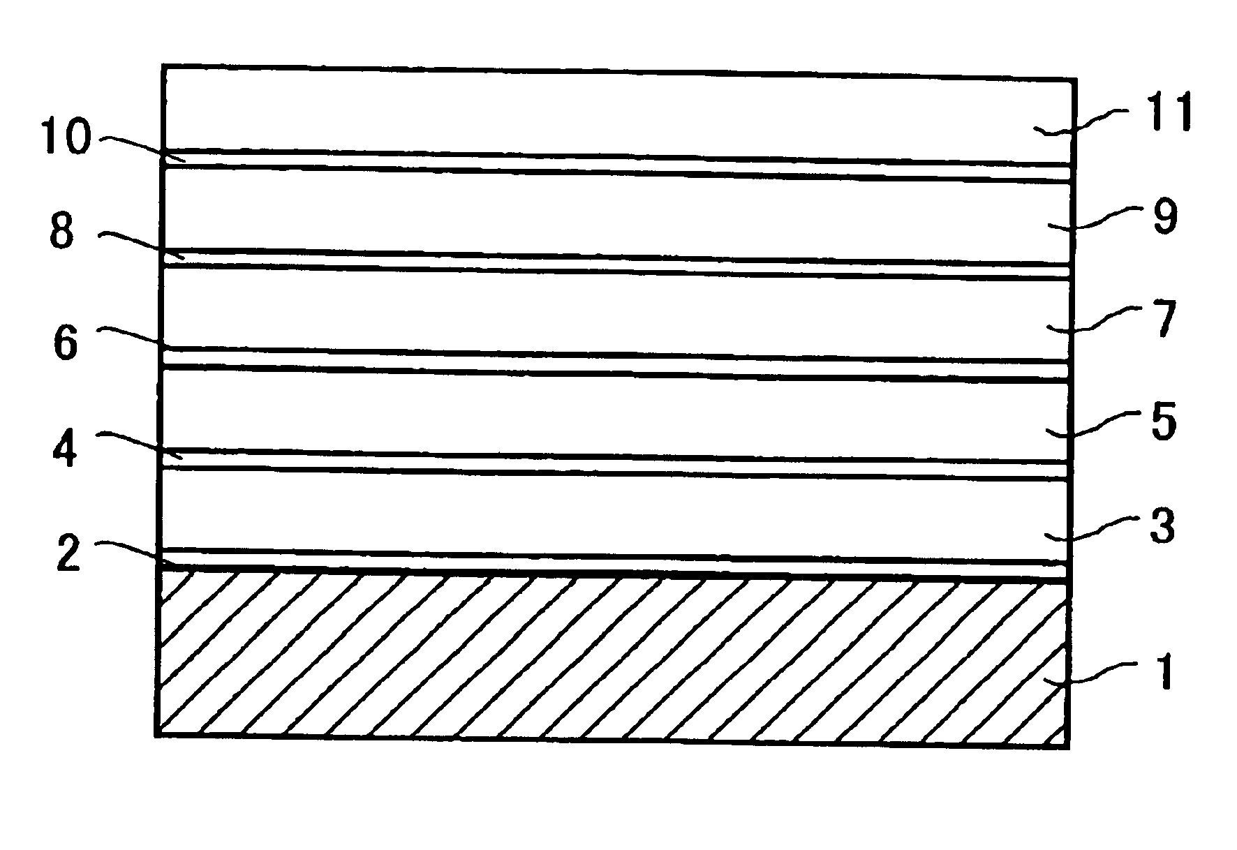
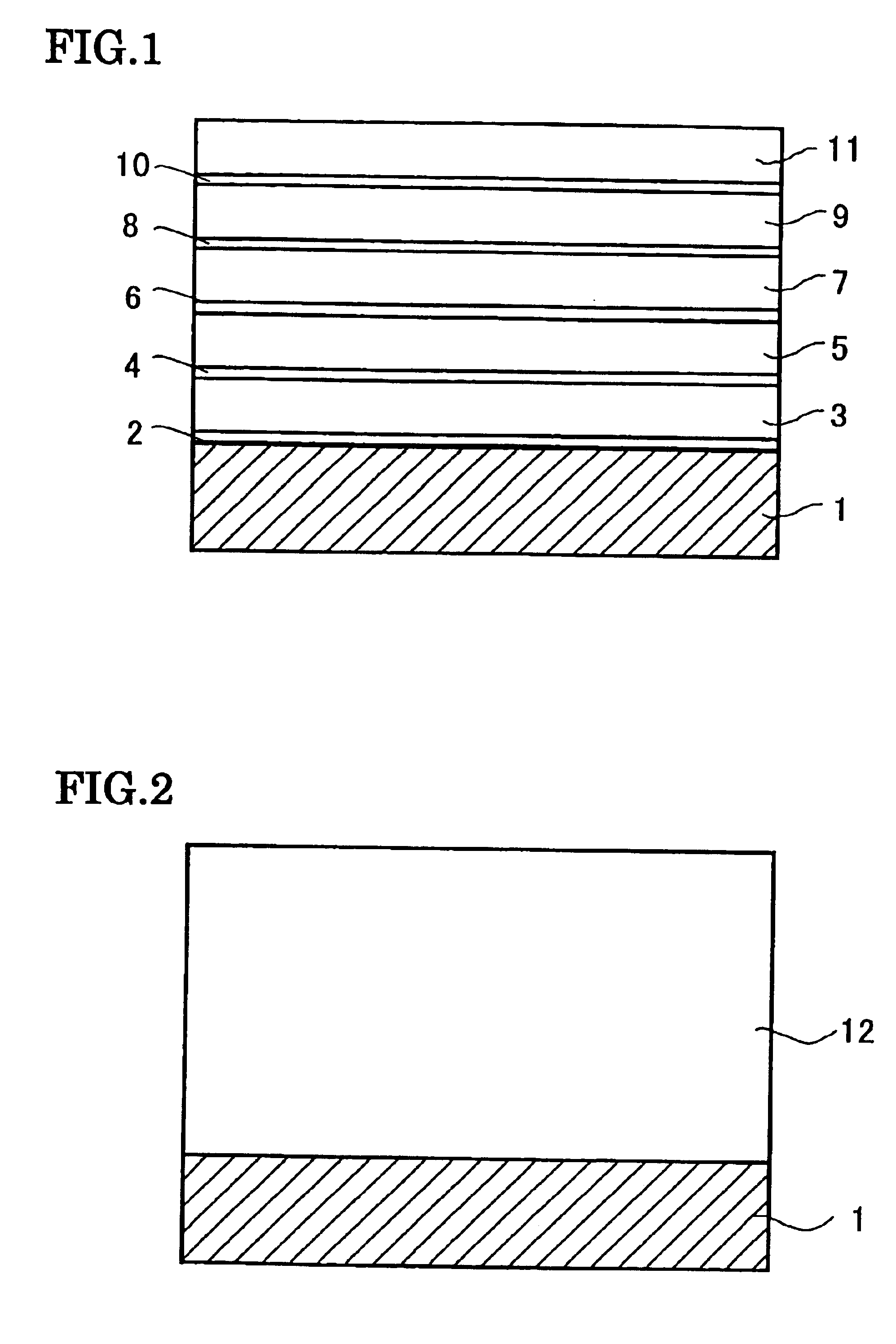
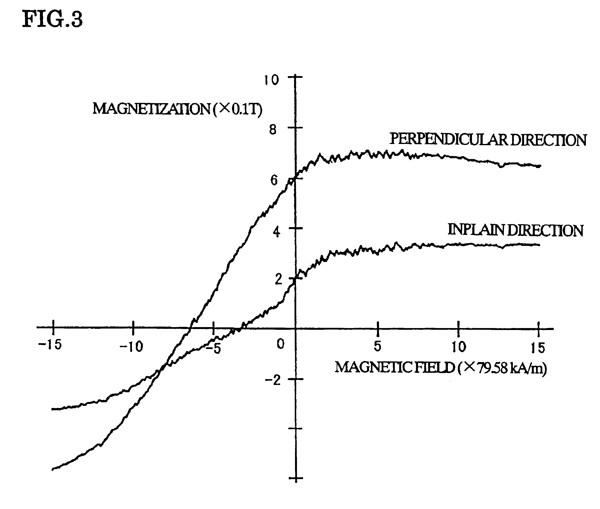
In this embodiment, first, on an Al.sub.2 O.sub.3 --TiC ceramic substrate which was heated at 550.degree. C., a plurality of samples in which refractory metal layers consisting of one kind of Ta, Mb, Zr, and Ti layers and Nd--Fe--B alloy layers (rare earth alloy magnetic layers) were alternately deposited were prepared by a DC diode magnetron sputtering apparatus. In this embodiment, for all of the samples, the total thickness of the Nd--Fe--B alloy layers was set to be 1000 nm (200 nm.times.5). The multilayer structure and the magnetic properties in the respective samples are shown in the following Table 1.

TABLE 1 Perpendicular to In-plane the film plan Br1 H.sub.cJ Br2 H.sub.cJ Sample No. Multilayer Structure (T) (kA / m) (T) (kA / m) 1 Comparative example Sub. / Nd--Fe--B (1000 nm) 0.20 263 0.61 509 2 Example of the invention Sub. / [Ti (20 nm) / Nd--Fe--B (200 nm)] .times. 5 0.25 422 0.89 844 3 Example of the invention Sub. / [Ta (20 nm) / Nd--Fe--B (200 nm)] .times. 5 0.11 422 0.88 >1194 4 E...

embodiment 2

In this embodiment, on an Al.sub.2 O.sub.3 --TiC ceramic substrate heated at 550.degree. C., a sample in which five Ta layers each having a thickness of 20 nm and five Pr--Fe--B alloy layers each having a thickness of 200 nm were alternately deposited, and a sample in which only a Pr--Fe--B alloy layer having a thickness of 1000 nm was formed by a DC diode magnetron sputtering apparatus were prepared. For respective samples, the multilayer structures and the magnetic properties are shown in the following Table 2.

TABLE 2 Perpendicular to In-plane the film plan Br1 H.sub.cJ Br2 H.sub.cJ Sample No. Multilayer Structure (T) (kA / m) (T) (kA / m) 14 Comparative example Sub. / Pr--Fe--B (1000 nm) 0.21 231 0.65 485 15 Example of the invention Sub. / [Ta (20 nm) / Pr--Fe--B (200 nm)] .times. 5 0.16 478 0.83 >1194

In the table, Sample No. 15 is an example of the present invention and Sample No. 14 is a comparative example.

For the deposition of the Ta layer, pure metal target was used. The deposition wa...

embodiment 3

In this embodiment, on an Al.sub.2 O.sub.3 --TiC ceramic substrate cooled by water, a sample in which five Ta layers each having a thickness of 20 nm and five Nd--Fe--B alloy layers each having a thickness of 200 nm were alternately deposited, and a sample in which only an Nd--Fe--B alloy layer having a thickness of 1000 nm was formed, by a DC diode sputtering method were prepared. For respective samples, the multilayer structures and the annealing conditions are shown in the following Table 3.

TABLE 3 Perpendicular to In-plane the film plan Br1 H.sub.cJ Br2 H.sub.cJ Sample No. Multilayer Structure (T) (kA / m) (T) (kA / m) 14 Comparative example Sub. / Pr--Fe--B (1000 nm) 0.21 231 0.65 485 15 Example of the invention Sub. / [Ta (20 nm) / Pr--Fe--B (200 nm)] .times. 5 0.16 478 0.83 >1194

In the table, Sample No. 17 is an example of the present invention and Sample No. 16 is a comparative example.

For the deposition of the Ta layer, pure metal target was used. The deposition was performed in cond...


PUM

PropertyMeasurementUnit
thicknessaaaaaaaaaa
thicknessaaaaaaaaaa
thicknessaaaaaaaaaa

Abstract

Refractory metal layers 2, 4, 6, 8, and 10, and rare earth alloy magnetic layers 3, 5, 7, 9, 11, and 12 are alternately deposited, so as to form a multilayer structure including four or more layers on a substrate. The refractory metal layers 2, 4, 6, 8, and 10 are formed from at least one kind of material selected from a group consisting of Ti, V, Cr, Zr, Nb, Mo, Hf, Ta, and W, and each has a thickness of not less than 5 nm nor more than 50 nm. The rare earth alloy magnetic layers 3, 5, 7, 9, 11, and 12 have tetragonal R2Fe14B (R is Nd and / or Pr) as a primary constituent phase, and each has a thickness of not less than 50 nm nor more than 500 nm.

Description

The present invention relates to a thin film permanent magnet and a method for producing the thin film. Particularly, the present invention relates to a thin film permanent magnet suitably used for a micro-motor, a micro-actuator, a device for applying a biased magnetic field to a magneto-resistive device, a magnetic recording medium, or the like.In the progress of miniaturization of various types of electrical apparatuses, the development of a micro-motor, a micro-actuator, and the like in which a thin film permanent magnet is employed is pursued. The size and the performance of a device of such a type depend on the magnetic properties of a thin film permanent magnet. For this reason, attention is focused, as a candidate material for the thin film permanent magnet on a Nd--Fe--B based magnet material and a Sm--Co based magnet material of which the maximum magnetic energy product is high, and the research and development on such materials are being extensively conducted. Among them,...

Claims


Application Information

Patent Timeline
Patent Type & Authority Patents(United States)
IPC IPC(8): G11B5/72G11B5/73H01F41/30H01F1/057H01F10/00G11B5/64H01F1/032H01F10/32H01F41/14G11B5/84G11B5/62H01F10/12C23C14/06C22C38/00C23C14/14G11B5/66H02K15/03
CPCB82Y25/00B82Y40/00G11B5/653G11B5/66H01F1/057H01F10/126H01F41/302G11B5/8404G11B5/72G11B5/7325Y10T428/1107Y10S428/90H01F10/3286G11B5/7368H01F10/14G11B5/672
Inventor UEHARA, MINORU
Owner SUMITOMO SPECIAL METAL CO LTD
Why Eureka
Try Eureka