Optical microswitch

a micro-switch and optical technology, applied in the field of optical switches, can solve the problems of large size, large cost of prior art electromechanical actuators, inaccurate mirror positioning, etc., and achieve the effects of large vertical electrode area, high stiffness, and low cost of prior art switches

Inactive Publication Date: 2004-12-28
COHERENT INC
View PDF37 Cites 3 Cited by
  • Summary
  • Abstract
  • Description
  • Claims
  • Application Information

AI Technical Summary

Benefits of technology

The early comb drive actuators used thin, polysilicon layers provided by the so-called surface micro-machining process to fabricate the comb fingers and the moveable, laterally-driven element. This polysilicon was typically 1-2 microns thick. Since the lateral feature size of these devices was comparable to the material thickness, the stiffness of the parts to out-of-plane deflections was very low. The advent of Deep Reactive Ion Etching (DRIE) has allowed similar structures to be fabricated in single crystal silicon with typical thicknesses of 100 microns. DRIE is described in a paper entitled, "Silicon Fusion Bond

Problems solved by technology

The prior art switches are very expensive and rather large.
Most of the prior art approaches have used a single electromechanical actuator, either a linear or angular actuator, to deflect the input optical beam because the prior art electromechanical actuators have b

Method used


Image

  • Optical microswitch
  • Optical microswitch
  • Optical microswitch

Examples


Embodiment Construction

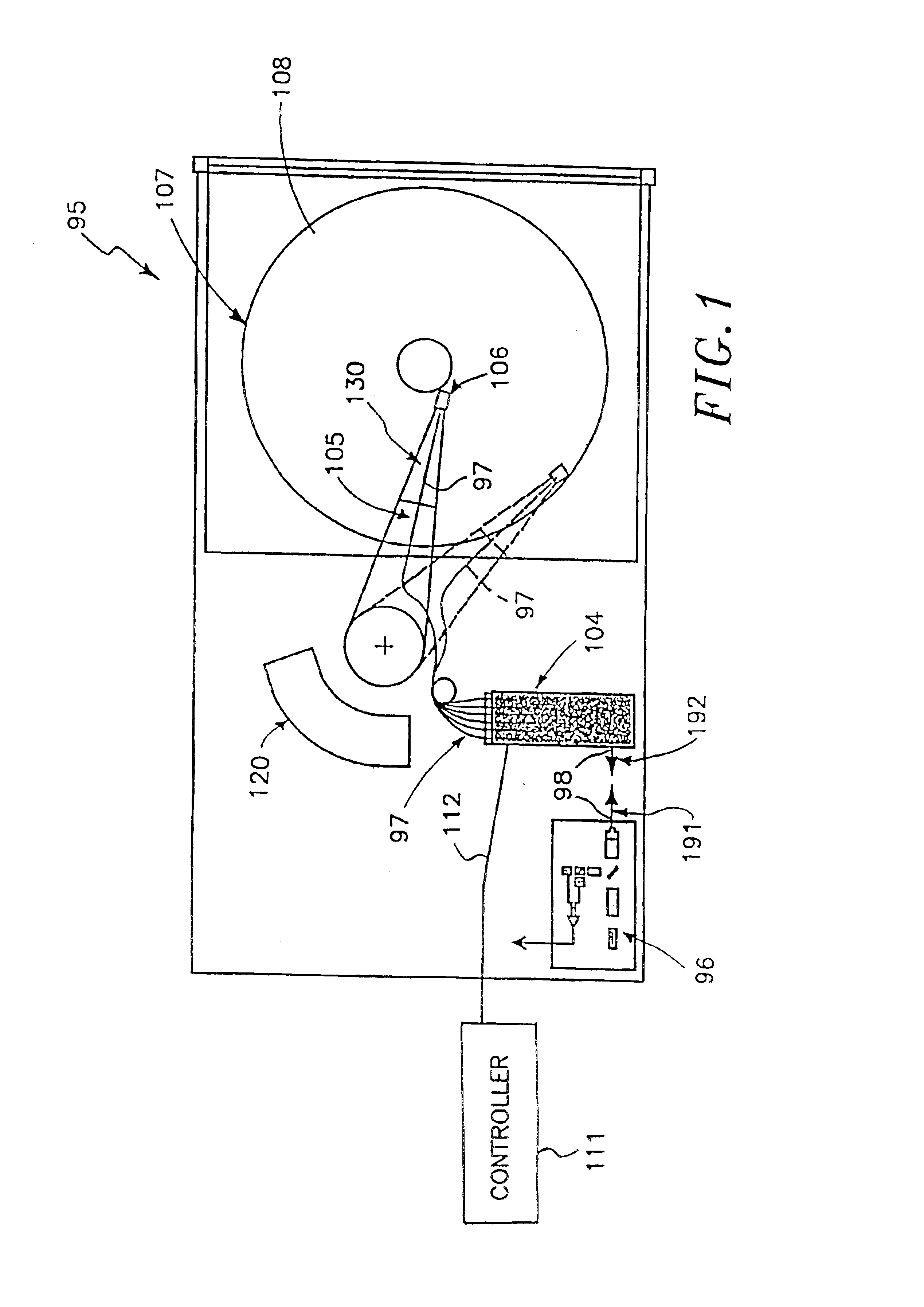
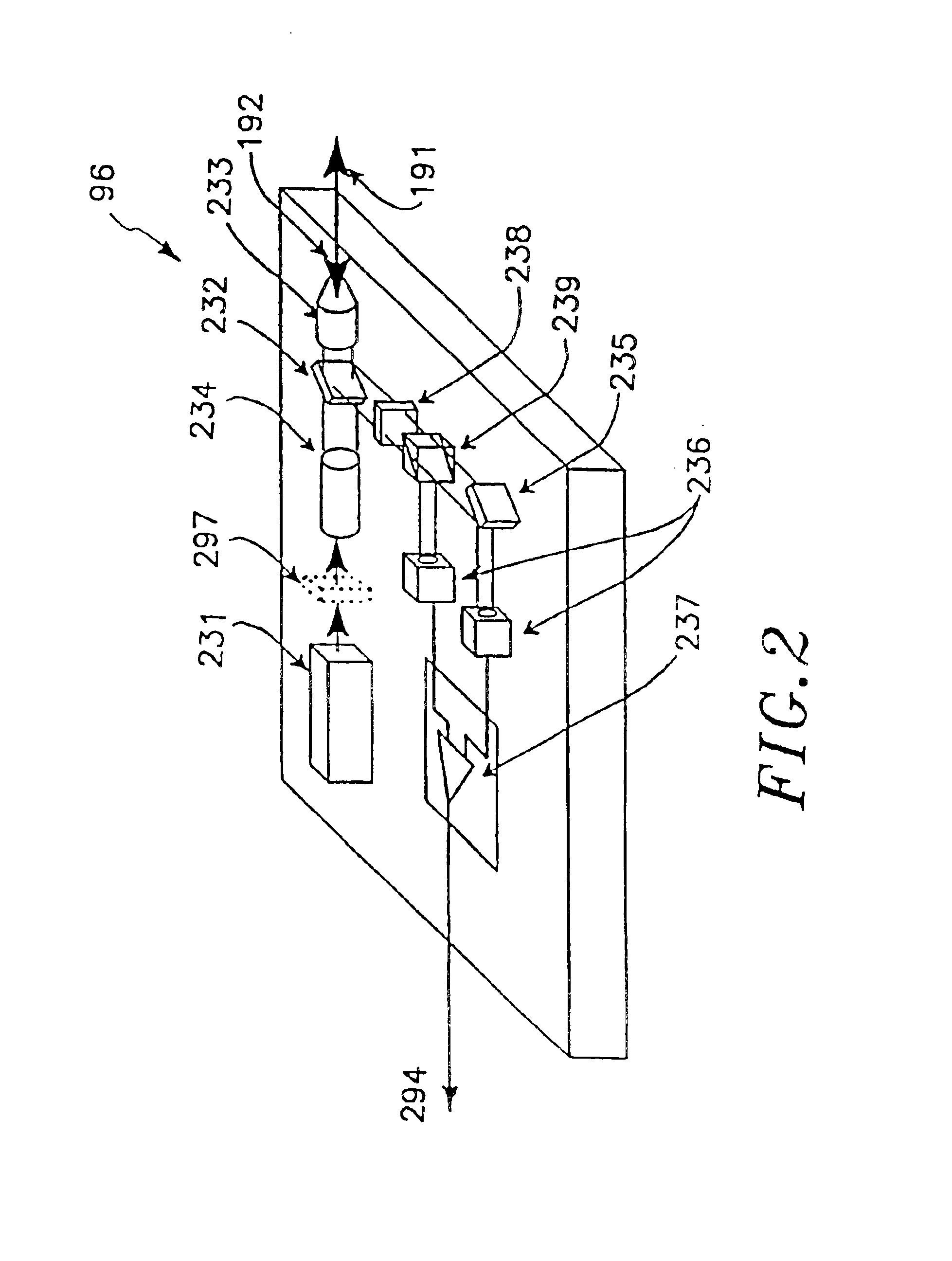
Referring now to the drawings, FIG. 11 is a plan view illustrating some of the basic elements of a magneto-optical (MO) data storage and retrieval system. Few specific details are identified in this and FIGS. 2 through 4 as they are intended to portray some of the basic elements of a functional system in which the present invention is useful. The invention is not limited to use in only one specific MO data storage system and, as discussed below, is not limited to use in MO data storage systems but can be used in telecommunications or other systems.

Referring to FIG. 1, the system 95 includes a set of flying heads 106 whose details will be described below that are adapted for use with a plurality of "N" MO discs 107. In a preferred embodiment, N equals six and thus a plurality of six discs 107 are provided in a stack (not shown). Each of the discs 107 is double sided and provided with first and second opposite planar surfaces 108. One flying head 106 is provided for each MO disc surfa...


PUM


Abstract

An optical microswitch for use with a laser beam that extends along a path comprising a body having an inlet port adapted to receive the laser beam and a plurality of outlet ports. A plurality of mirrors coupled to a plurality of micromotors carried by the body. The micromotors selectively move the mirrors from a first position out of the path of the laser beam to a second position into the path of the laser beam to direct the laser beam to one of the outlet ports. Each of the micromotors has at least one electrostatically-driven comb drive assembly therein for moving the respective mirror to one of the first and second positions. A controller is electrically coupled to the micromotors for providing control signals to the micromotors.

Description

SCOPE OF THE INVENTIONThe present invention relates generally to optical switches and more particularly to optical switches having a plurality of movable mirrors.There has been considerable interest in switches for switching light from one optical fiber to another or from a free space optical beam to one or more optical fibers, particularly for telecommunications and digital data networking. A variety of switch configurations are of interest, including 1.times.2, 1.times.n, and n.times.n, where n is a number from 2 to about 64. A variety of principles have been utilized in prior art switches, including electro-optical effects and electromechanical actuators, and working switches are now commercially available using these techniques. The prior art switches are very expensive and rather large.Prior art 1.times.n electromechanical optical fiber switches have typically either moved the input fiber so that it is in communication with the desired output fiber, moved a single mirror so tha...

Claims


Application Information

Patent Timeline
IPC IPC(8): G02B26/08G02B6/35G02B6/42G11B11/105G11B11/00G11B7/135H02N1/00G11B7/0037G11B7/00G11B7/085G11B7/12
CPCH02N1/008G02B6/4216G02B26/0833G02B26/0841G11B7/122G11B7/1362G11B7/1384G11B11/10543G02B6/3548G02B6/3518G02B6/357G02B6/3582G02B6/3584G11B7/0037G11B7/08564G11B11/1058
Inventor JERMAN, JOHN H.GRADE, JOHN D.DRAKE, JOSEPH D.PETERSEN, KURT E.
Owner COHERENT INC
Why Eureka
Try Eureka