Ring optical interferometer

Inactive Publication Date: 2005-01-04
VENTURE ASTRA
View PDF8 Cites 6 Cited by
  • Summary
  • Abstract
  • Description
  • Claims
  • Application Information

AI Technical Summary

Benefits of technology

The present invention embodies an overall functional approach to the design and construction of very large sparse array telescopes in the form of a multi-aperture interferometric optical system. The invention implements an approach that explicitly negates the classic telescope design notion of forming a singular image through coherent beam combination, which works well in a laboratory at smaller scales. The invention implements a field-variant object-space sampling approach much more akin

Problems solved by technology

With only a few exceptions, which tend to be classic optical interferometers in character, the sheer cost and complexity of actually building, testing, launching, and operating sparse array telescopes have, to date, permitted production of no known op

Method used


Image

  • Ring optical interferometer
  • Ring optical interferometer
  • Ring optical interferometer

Examples


Embodiment Construction

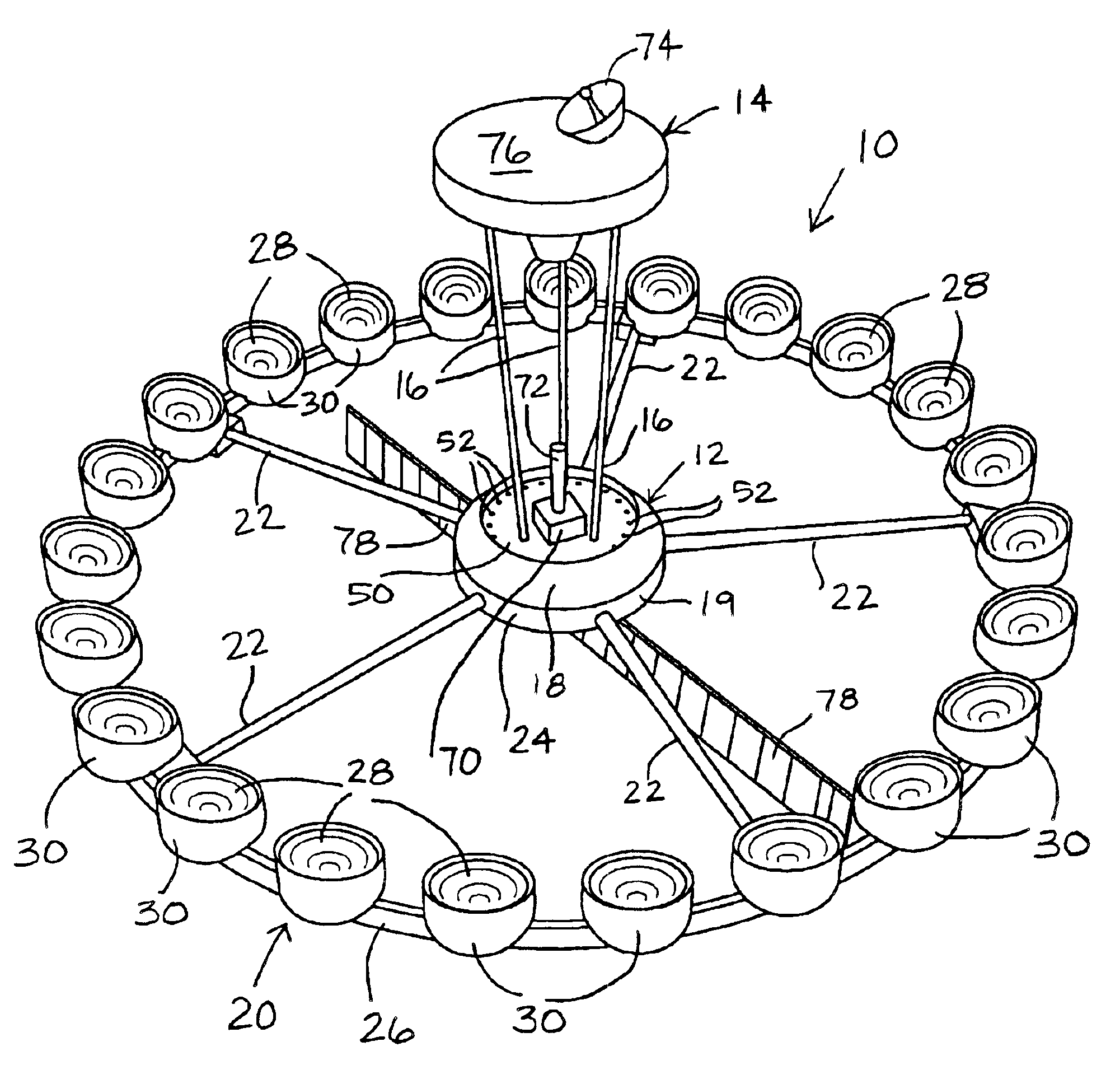
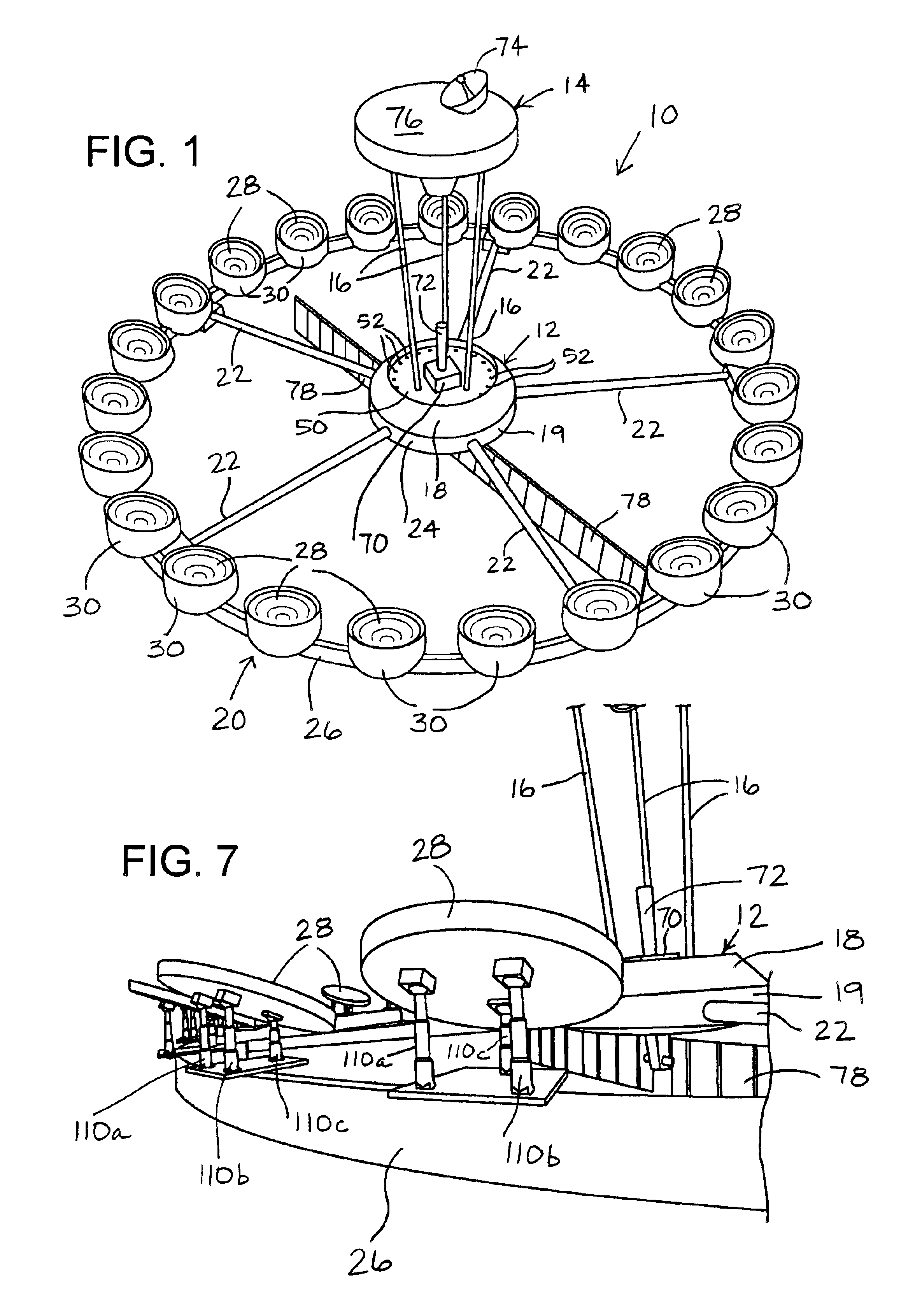
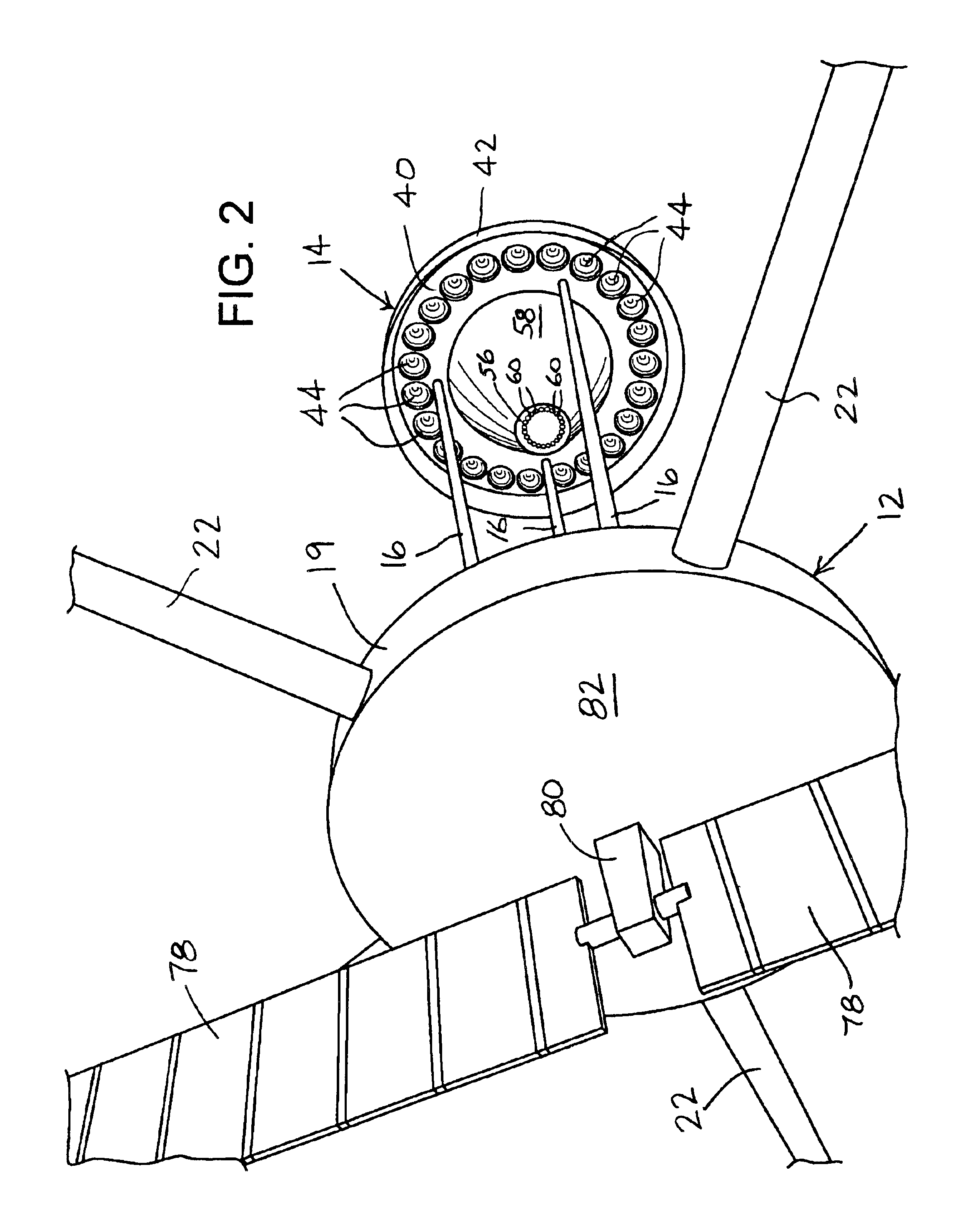
FIGS. 1 and 2 show an isometric view and an enlarged, fragmentary rearward view, respectively, of a preferred embodiment of an orbiting multi-aperture interferometric optical system 10 constructed in accordance with the invention. With reference to FIGS. 1 and 2, optical system 10 is composed of a main body in the form of a central hub 12 and a secondary assembly in the form of a plate structure 14 spaced apart from each other by connection to the opposite ends of three cylindrical columns 16. Central hub 12 is composed of two separate cylindrical structures 18 and 19, the larger structure 18 containing most of the satellite equipment and the smaller structure 19 providing an anchor for a primary mirror structure 20 and containing a multi-spectral primary optical detector. Four mirror ring structures, two each connected to central hub 12 and plate structure 14, direct incoming light to the multi-spectral primary optical detector positioned at a detector plane on central hub 12.

FIG. ...


PUM


Abstract

A multi-aperture interferometric optical system collects light propagating from a source of light and develops overlapping diffraction patterns on an optical detector that produces output signals for processing to form an image corresponding to the diffraction patterns. A preferred embodiment of the invention is a large aperture orbiting, earth-watching ring interferometric optical system configured such that there is no macro-structure pointing. Four mirror-ring structures direct incoming light to a multi-spectral primary optical detector that acquires light-pattern information from which an image can be derived.

Description

TECHNICAL FIELDThis invention relates to large aperture optical systems adapted to form high resolution images of distant extended scenes and, in particular, to a multi-aperture interferometric optical system that collects light propagating from a source of light and develops a diffraction pattern on an optical detector that produces output signals for processing to form an image corresponding to the diffraction pattern.BACKGROUND OF THE INVENTIONThe theoretical advantages of placing telescopes above the distorting atmosphere have been well known and practically pursued for about four or more decades. Briefly stated, these advantages include sharper images and accessibility to a broader range of wavelengths. The Hubble Space Telescope and NASA's upcoming NGST (Next Generation Space Telescope) are particularly well known examples of spaceborne telescopes. Remote sensing satellites beginning with Landsat and Spot, and more recently systems launched and operated by Space Imaging, Digit...

Claims


Application Information

Patent Timeline
IPC IPC(8): G02B17/06G02B23/16G02B17/00G02B23/02G01J1/20G01J9/02G02B5/08G02B7/182G02B21/18G02B23/06G02B27/58
CPCG02B17/0663G02B27/58G02B23/06G02B23/16G02B23/02G01J2009/0273
Inventor RHOADS, GEOFFREY B.
Owner VENTURE ASTRA
Why Eureka
Try Eureka