Cooling device and an electronic apparatus including the same

a cooling device and electronic technology, applied in the direction of power cables, cables, semiconductor/solid-state device details, etc., can solve the problems of large and complicated device structure, increased heat generation of cpu, and insufficient conventional air cooling methods solely dependent on heat sinks. , to achieve the effect of simple construction, reduced size and thickness of the apparatus, and low cos

Inactive Publication Date: 2005-01-04
PANASONIC CORP
View PDF23 Cites 70 Cited by
  • Summary
  • Abstract
  • Description
  • Claims
  • Application Information

AI Technical Summary

Benefits of technology

Thus, the size and thickness of the apparatus are decreased so that the electronic apparatus featuring a simple construction and low costs is provided.

Problems solved by technology

As a result, heat generation of the CPU is increased so much that the conventional air cooling method solely dependent upon a heat-sink has become inadequate.
Since the cooling device comprises the combination of these elements, the device has a large and complicated structure which cannot be downsized and also involves cost increase.
In other words, the first conventional cooling device is basically suited for cooling large electronic apparatuses but is not adapted for the current high-performance portable notebook computers featuring a compact, lightweight and slim design and various modes of carriage and use.
That is, the headers are an impediment to a thinner design of the notebook computer.
Unfortunately, the thickness of the reciprocating pump defines a great thickness of the radiator header 114 as a whole, making the notebook computer of slim design impracticable.
Further, the slim notebook computer does not permit the heat absorber header 113 to accommodate the reciprocating pump of the second cooling device.
In addition, vibrations and noises produced by the reciprocating pump adversely affect the semiconductor heat generating device 110 on which the pump would be mounted.
In some cases, the noises may grate on ear.
On these accounts, it is difficult for the second cooling device to contribute the slim design.
The second conventional cooling device encounters a limited cooling capability because the radiator header 114 in contact with the wall of the metal housing 116 has a low heat transferability resulting from a small heat radiating area.
Furthermore, assembly work for the cooling device is complicated.
Thus, the second conventional cooling device has limitations in the reduction of size and thickness of the notebook computers.
The second conventional cooling device with such drawbacks falls short of meeting a demand for further increase of the cooling capability in conjunction with the recent progress of the CPUs.
On the other hand, the conventional pump with the heat exchange function has a large, complicated structure requiring the cooling water passage disposed therein because the coolant is cooled by the independent cooling water.
Hence, the pump is a complicated system difficult to be downsized and also suffers a large number of components and low assembly efficiencies.
Consequently, a good thermal efficiency or cost reduction cannot be expected from this pump.

Method used


Image

  • Cooling device and an electronic apparatus including the same
  • Cooling device and an electronic apparatus including the same
  • Cooling device and an electronic apparatus including the same

Examples


first embodiment

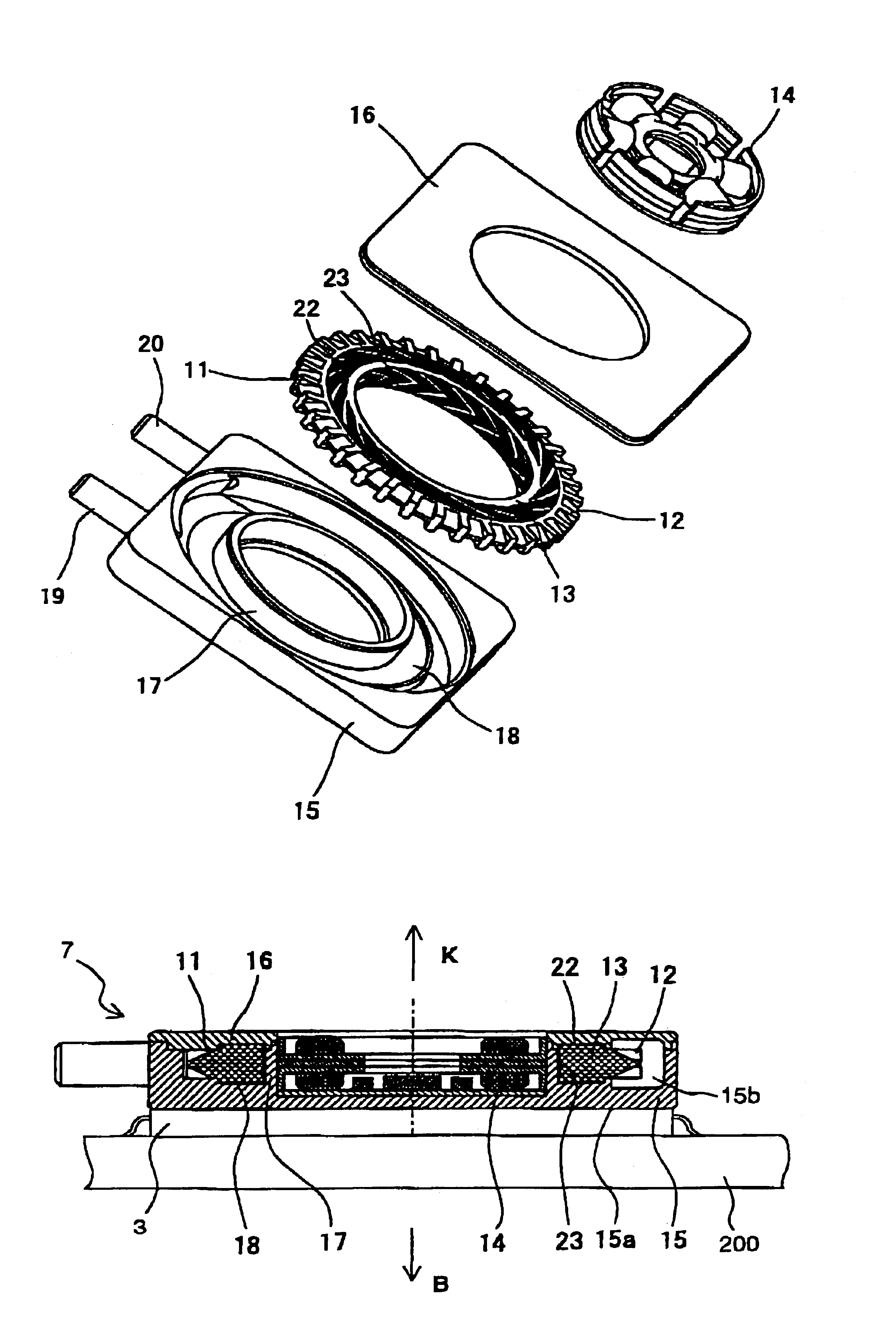
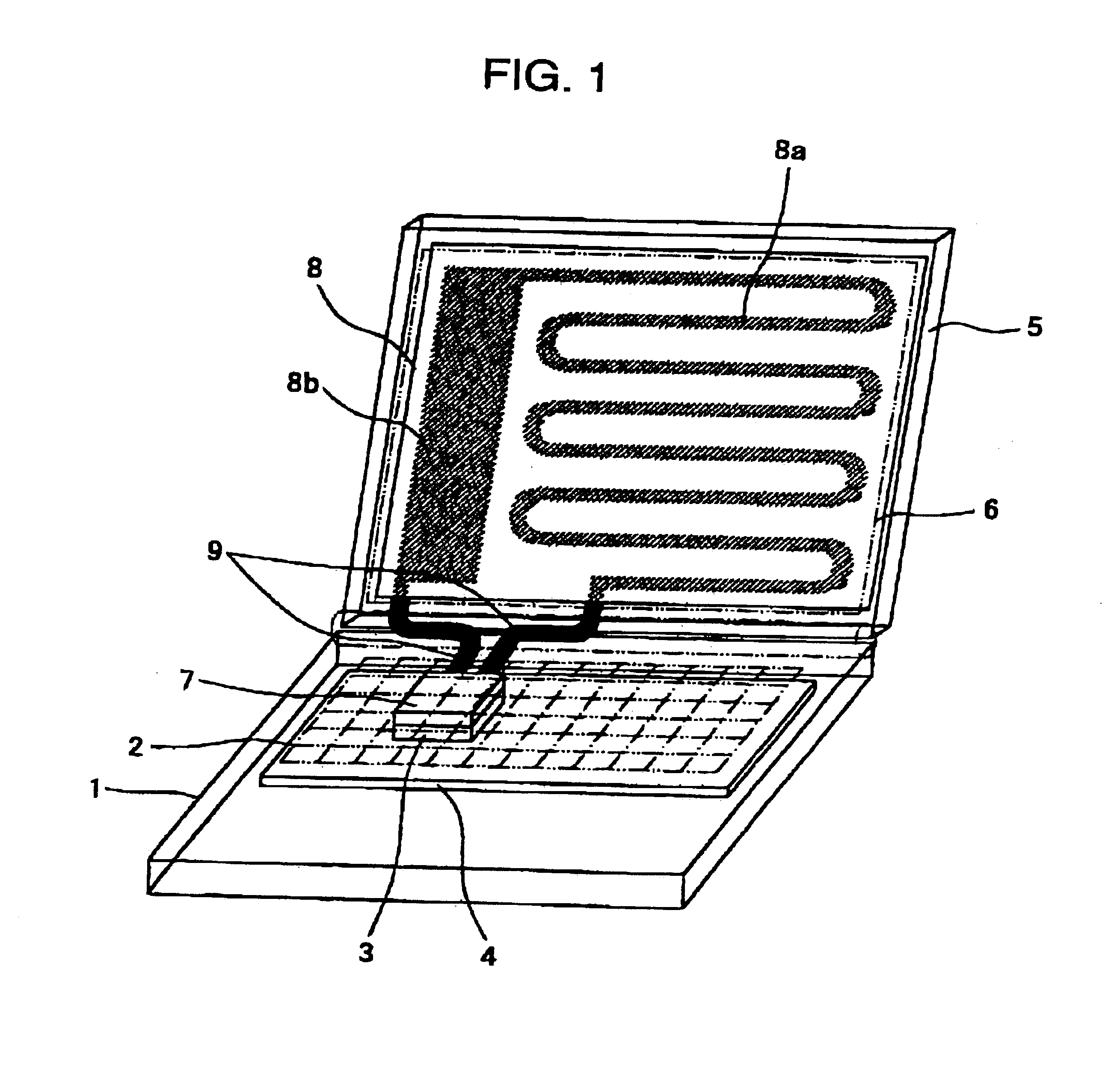
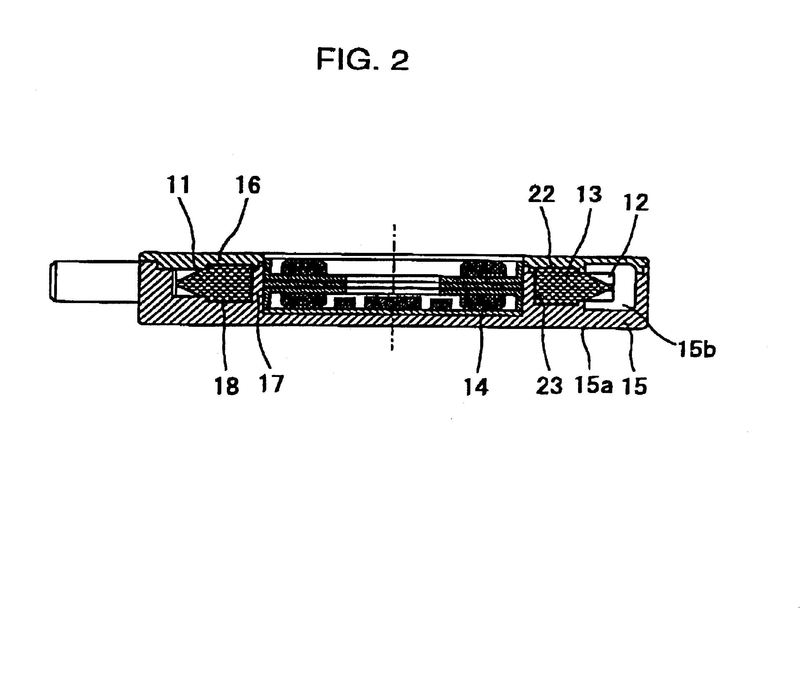
A cooling device of a first embodiment and an electronic apparatus including the same is designed to interconnect a pump of contact heat exchanger type and a radiator by means of a flexible pipe permitting a second housing to rotate relative to a first housing. The electronic apparatus is a foldable apparatus such as a notebook computer. FIG. 1 is a diagram showing a general construction of the electronic apparatus incorporating the cooling device of the first embodiment, whereas FIG. 2 is a sectional view showing the pump of contact heat exchanger type according to the first embodiment. FIG. 3 is a disassembled perspective view showing the pump of contact heat exchanger type according to the first embodiment whereas FIG. 4 is a sectional view of a principal part showing a flow of a coolant in the pump according to the first embodiment.

Referring to FIG. 1, a reference numeral 1 represents a first housing such as of a notebook computer; a numeral 2 representing a key board disposed o...

second embodiment

A cooling device according to a second embodiment of the invention and an electronic apparatus including the same is designed to interconnect a pump of contact heat exchanger type and a radiator by means of a pipe and a pivotal member permitting the second housing to rotate relative to the first housing. The electronic apparatus is a foldable apparatus such as a notebook computer. The pump of contact heat exchanger type is constructed the same way as in the first embodiment. FIG. 7 is a diagram showing a general construction of the electronic apparatus incorporating the cooling device according to the second embodiment of the invention. FIG. 8 is a sectional view showing the pivotal member according to the second embodiment of the invention. FIG. 9 is a sectional view showing the pivotal member of the second embodiment of the invention integrated with a removable snap-in type connector.

Referring to FIG. 7, the reference numeral 1 represents the first housing; the numeral 2 represent...

third embodiment

The internal configuration of a centrifugal pump 300 of the third exemplary embodiment is now described with reference to FIGS. 38 through 42B. An open-type impeller 301 of the centrifugal pump has a through-hole 301a formed therein and open vanes 302. A magnet rotor 303 is provided along an outer periphery of the impeller 301. A stator 304 is provided inside of the magnet rotor 303. A housing 305 of the pump accommodates the impeller 301, and restores a pressure of kinetic energy given by the impeller 301 to fluid, thus guiding the fluid to an outlet port linked to an outlet passage 310. The housing 305 has a heat-generating electronic component 400 attached thereto, such as an IC, an LSI, or an MPU.

A pump chamber 305a restores a pressure of kinetic energy given by the vanes 302, thus guiding the fluid to the outlet port. A heat-absorbing surface 305b is provided on a side face of the housing 305 along the pump chamber 305a. The heat-absorbing surface deprives the heat-generating e...


PUM


Abstract

A pump for circulating a coolant has a housing thereof in direct thermal connection with an electronic component. This provides both the improvement of cooling efficiency of a cooling device and the realization of a compact, slim design of the device.

Description

BACKGROUND OF THE INVENTION1. Field of the InventionThe present invention relates to a cooling device adapted to circulate a coolant for cooling a heat generating electronic component such as a central processing unit (hereinafter referred to as CPU) disposed in a housing, as well as to an electronic apparatus including the same.2. Description of the Related ArtThe recent years have seen a dramatic progress in the speed-up of computers while CPUs have much greater clock frequencies than before. As a result, heat generation of the CPU is increased so much that the conventional air cooling method solely dependent upon a heat-sink has become inadequate. In this context, a high-efficiency, high-power cooling device is absolutely required. Known as such a cooling device are those disclosed in Japanese Unexamined Patent Publication Nos. 264139 / 1993 and 32263 / 1996 wherein a coolant is circulated on a substrate for cooling the substrate with a heat generating electronic component mounted th...

Claims


Application Information

Patent Timeline
Patent Type & Authority Patents(United States)
IPC IPC(8): G06F1/20H05K7/20F28D15/02
CPCF28D15/0266G06F1/203G06F2200/203G06F2200/201
Inventor NIWATSUKINO, KYOHIROSE, MASASHINARAKINO, SHIGERUAIZONO, YOSHIMITSUKASAHARA, KAZUYUKIKOGA, SHINYASAKAI, TOSHISUKEKUBOTA, TOSHIYUKI
Owner PANASONIC CORP
Why Eureka
Try Eureka