Displacement unit

a technology of displacement unit and displacement chamber, which is applied in the direction of automatic control device, feeding apparatus, programme control, etc., can solve the problems of inability to produce such assembly machines using standardized individual components, inability to intervene, and inability to manufacture such assembly machines, so as to achieve the effect of reducing programming costs, avoiding expensive wiring installation, and improving accessibility to individual components in the region of the machin

Inactive Publication Date: 2005-01-11
STICHT WALTER
View PDF18 Cites 9 Cited by
  • Summary
  • Abstract
  • Description
  • Claims
  • Application Information

AI Technical Summary

Benefits of technology

The object of the invention is achieved according to one aspect thereof with a displacement unit for a manipulation system, which comprises components which are adjustable relative to each other, a guiding device for guiding the components, and a control unit. The control unit has a pressure fluid control valve for actuating one of the components by the pressure fluid, and a control module cooperating with the pressure fluid control valve and comprising a logic unit, the control module being connectable to a central control unit by interface. The control unit is integrated into one of the components. The surprising advantage is that the control unit is connected directly to the displacement unit and thus expensive installation of wiring can be avoided on the one hand and specific functions of the adjusting unit can be preset without external programming. In this way for example the expense of programming can be reduced considerably and it is possible to produce the transport devices in series as standard units without the special manufacture of parts designed for specific uses being necessary. In addition, accessibility to the individual components in the region of a machine is considerably improved if the two supply lines leading from the pressure fluid control valve to the drive unit are omitted by integrating the pressure fluid control valve into the drive unit or the components. A further advantage is the short lines which prevents undesired damping caused by the elastic stretching of the feed lines, friction losses etc., resulting in a considerable improvement in switching times, reaction times etc.
The object is also achieved according to another aspect of the invention with a displacement for a manipulation system, which comprises components which are adjustable relative to each other, a pressure fluid drive for adjusting the components, the device having an outer surface, a guiding device for one of the components, and a control unit. The control unit has a pressure fluid control valve connected to the drive for actuating the drive by the pressure fluid, a control module cooperating with the pressure fluid control valve and comprising a logic unit, the control module being connectable to a central control unit by an interface, and a display element. The pressure fluid control valve and the control module are mounted on the outer surface of the drive. In addition to the advantages described hereinabove, a surprising advantage over and above the overall effect can be achieved in that the short switching times and ways of optimizing the overall displacement sequence can be combined with the thereby achievable greater availability.

Problems solved by technology

The disadvantage of this design is that the individual workstations comprise various different components according to the work to be performed, which excludes the serial manufacture of the various components.
In this way it is not possible to produce such an assembly machine using standardized individual components, which is disadvantageous for the manufacturing costs of such an assembly machine.
A further disadvantage is that once a production process has been commenced it is not possible to intervene to correct an erroneous protocol for example.
Furthermore, the central monitoring or direct programming of a particular workstation is not possible for example with an additional simulation procedure.

Method used


Image

  • Displacement unit
  • Displacement unit
  • Displacement unit

Examples


Embodiment Construction

First of all it should be noted that in the descriptions of the various embodiments the same parts are given the same reference numbers or component names, whereby the disclosures contained throughout the description can be applied to the same parts with the same reference numbers or the same component names. Also the details relating to position, such as e.g. top, bottom, side etc. relate to the Figure being described and should be transposed to a new position when the position has changed. Furthermore, individual features of the various embodiments shown can represent independent solutions according to the invention.

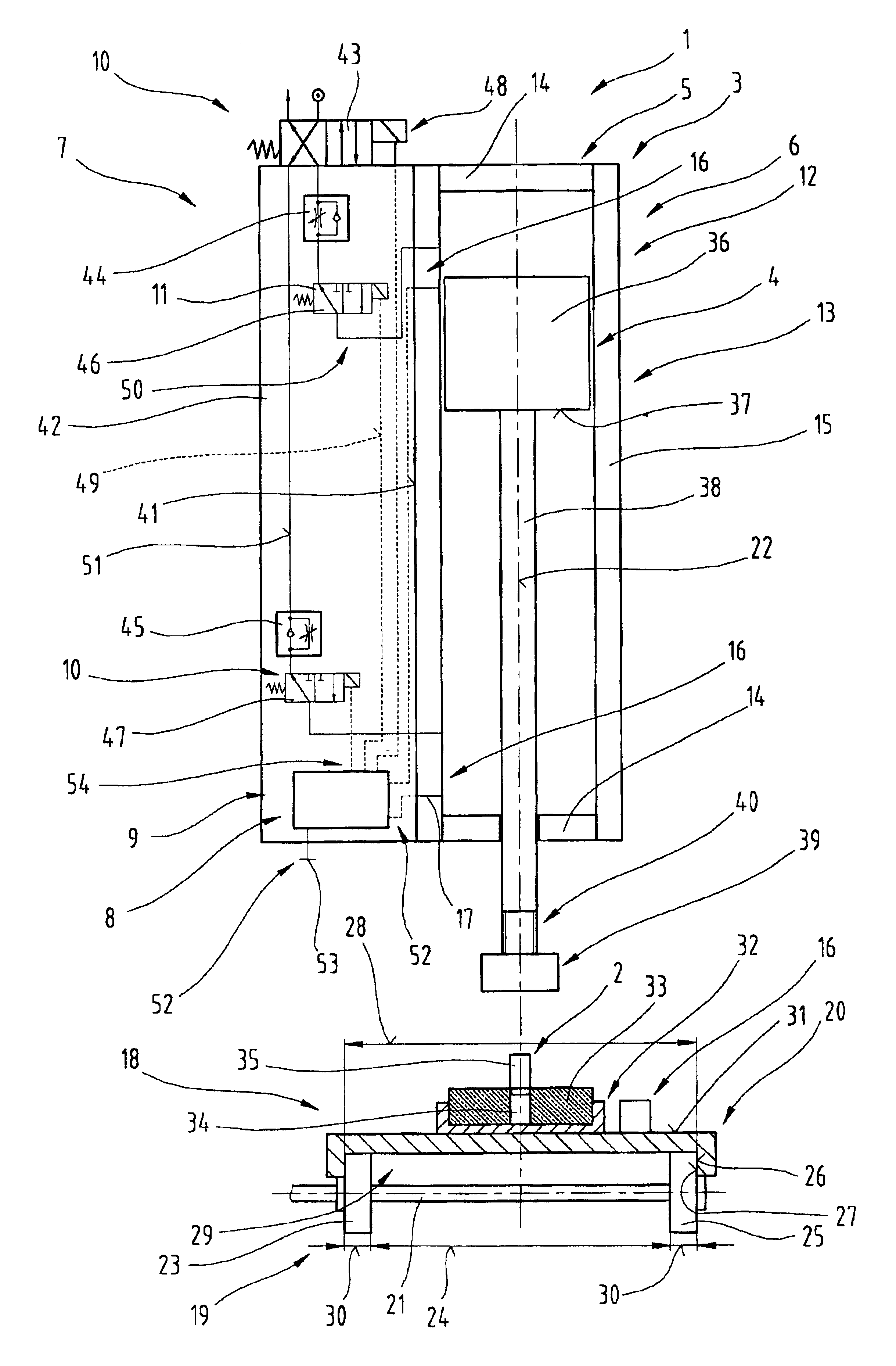
In FIG. 1 a displacement unit 1 for example for supply, manipulation, joining or control systems of an assembly system for assembly parts 2 is shown. The unit comprises components 3, 4 that can be displaced relative to one another using a drive unit 5, for example by means of compressed air, electricity or hydraulic fluid. Furthermore, the displacement unit 1 comprises...


PUM

PropertyMeasurementUnit
displacementaaaaaaaaaa
pressureaaaaaaaaaa
displacement parametersaaaaaaaaaa

Abstract

The invention describes a displacement unit (1) for example for supply, manipulation, guiding or control systems of mounting parts (2), with components (3, 4) that can be adjusted relative to one another by means of a drive unit (5) and with at least one guiding device (6) for at least one of the components (3; 4) and a control unit (7). At least one member (8) of the control unit (7) used for processing logic information or bus information is integrated into the drive unit (5) and/or into at least one of the components (3; 4) and/or is mounted on one of the components (3; 4).

Description

BACKGROUND OF THE INVENTION1. Field of the InventionThe invention relates to a displacement unit for a manipulation system.2. The Prior ArtFrom DE 41 06 689 Al a method for controlling a processing machine is known, in particular an assembly machine and similar processing machine. The latter comprises a plurality of workpiece carriers, which are moved past workstations on a moving track or work line in transport direction. The latter are designed respectively for at least one prespecified procedure and are controlled at least partly by an electronic control unit. Each workstation has its own electronic control unit, which is equivalent to the control units of other workstations, whereby the control unit of each workstation only cooperates with the immediately following and / or immediately preceding workstation via a data and control line. At the first workstation an electronic protocol is established for each workpiece carrier, which in addition to an identification identifying or ch...

Claims


Application Information

Patent Timeline
Patent Type & Authority Patents(United States)
IPC IPC(8): G05B19/00G05B19/414G05B19/43G05B19/44
CPCG05B19/414G05B19/4141G05B19/43G05B19/44Y10T29/53061G05B2219/34191G05B2219/45055Y10T29/53039G05B2219/31031Y02P90/02
Inventor STICHT, WALTER
Owner STICHT WALTER
Why Eureka
Try Eureka