Emission control apparatus for marine generator engine

a generator engine and emission control technology, applied in mechanical equipment, machines/engines, separation processes, etc., can solve the problems of insufficient attention to the challenges, the failure to effectively control the pollution of marine generator engines, and the life-threatening situation, so as to reduce the relatively high concentration of pollutants

Inactive Publication Date: 2005-01-11
ENVIROELEVATOR
View PDF24 Cites 2 Cited by
  • Summary
  • Abstract
  • Description
  • Claims
  • Application Information

AI Technical Summary

Benefits of technology

The invention relates to an apparatus for reducing the concentration of pollutants in the exhaust emissions of an internal combustion engine, particularly an engine driving an electric generator on a boat. The invention is particularly adapted for connecting to the exhaust manifold of a marine electric generator engine.
Therefore it is an object of the present invention to provide an apparatus and method for reducing the relatively high concentration of pollutants in the exhaust emissions of marine electric generator engines.
It is another object of the invention to provide an apparatus resistant to overheating that is capable of reducing the concentration of pollutants in the exhaust emissions of an internal combustion engine.
These and other objectives of the present invention are achieved by providing an apparatus for reducing pollutants in internal combustion engine emissions having a treatment chamber including an intake opening and an exhaust opening at opposing lateral ends of the treatment chamber. The intake opening receives a stream of gaseous emissions from the engine, which exits from the treatment chamber through the exhaust opening. A metal tube is disposed within the treatment chamber, and an electrode is disposed within the metal tube in spaced apart relation to the metal tube. The electrode is encircled by the metal tube so that, upon applying a voltage to the electrode, an arc is generated across the space between the electrode and the metal tube, the metal tube providing potential points of contact for the arc around the periphery thereof. The arc is generated from the electrode to the metal tube at a predetermined frequency to promote a chemical reaction that reduces the concentration of pollutants in the stream within the treatment chamber.
A preferred method for reducing pollutants in internal combustion engine emissions according to the invention comprises the steps of providing an apparatus including a treatment chamber having an intake opening and an exhaust opening, and a metal tube disposed within the treatment chamber. An electrode is disposed within the metal tube in spaced apart relation to the metal tube. The electrode is encircled by the metal tube so that, upon applying a voltage to the electrode, an arc is generated across the space between the electrode and the metal tube. The metal tube provides potential points of contact for the arc around its periphery. The arc is generated from the electrode to the metal tube at a predetermined frequency to promote a chemical reaction reducing the concentration of pollutants in the stream within the treatment chamber. The intake opening is connected to an exhaust manifold of the engine so that a stream of gaseous emissions passes from the exhaust manifold through the intake opening into the treatment chamber. A supplemental stream of air is supplied to the treatment chamber for diluting the stream of gaseous emissions within the treatment chamber. A voltage is pulsed at a predetermined frequency to the electrode to generate the chemical reaction with the stream of gaseous emissions as the stream passes proximate the metal tube to reduce the concentration of pollutants in the stream.

Problems solved by technology

It is well known that internal combustion engines produce an exhaust emission containing pollutants that are harmful to the environment.
Pollution control for marine electric generator engines presents a unique set of challenges that have not been sufficiently addressed by the prior art.
The collection of toxic pollutants such as carbon monoxide near swimmers, particularly children, presents a potentially life-threatening situation making effective pollution control of marine generator engines critical.
Conventional catalytic converters used on automobiles reach extremely hot temperatures of over 1000° Fahrenheit, which is too high for safe use on a boat where the risk of fire is of more paramount concern.
Other emission control devices, such as the ones disclosed in U.S. Pat. Nos. 5,410,871 and 5,419,123 operate at cooler temperatures, but still reach over 300° Fahrenheit, which presents a danger of overheating and fire.

Method used


Image

  • Emission control apparatus for marine generator engine
  • Emission control apparatus for marine generator engine
  • Emission control apparatus for marine generator engine

Examples


Embodiment Construction

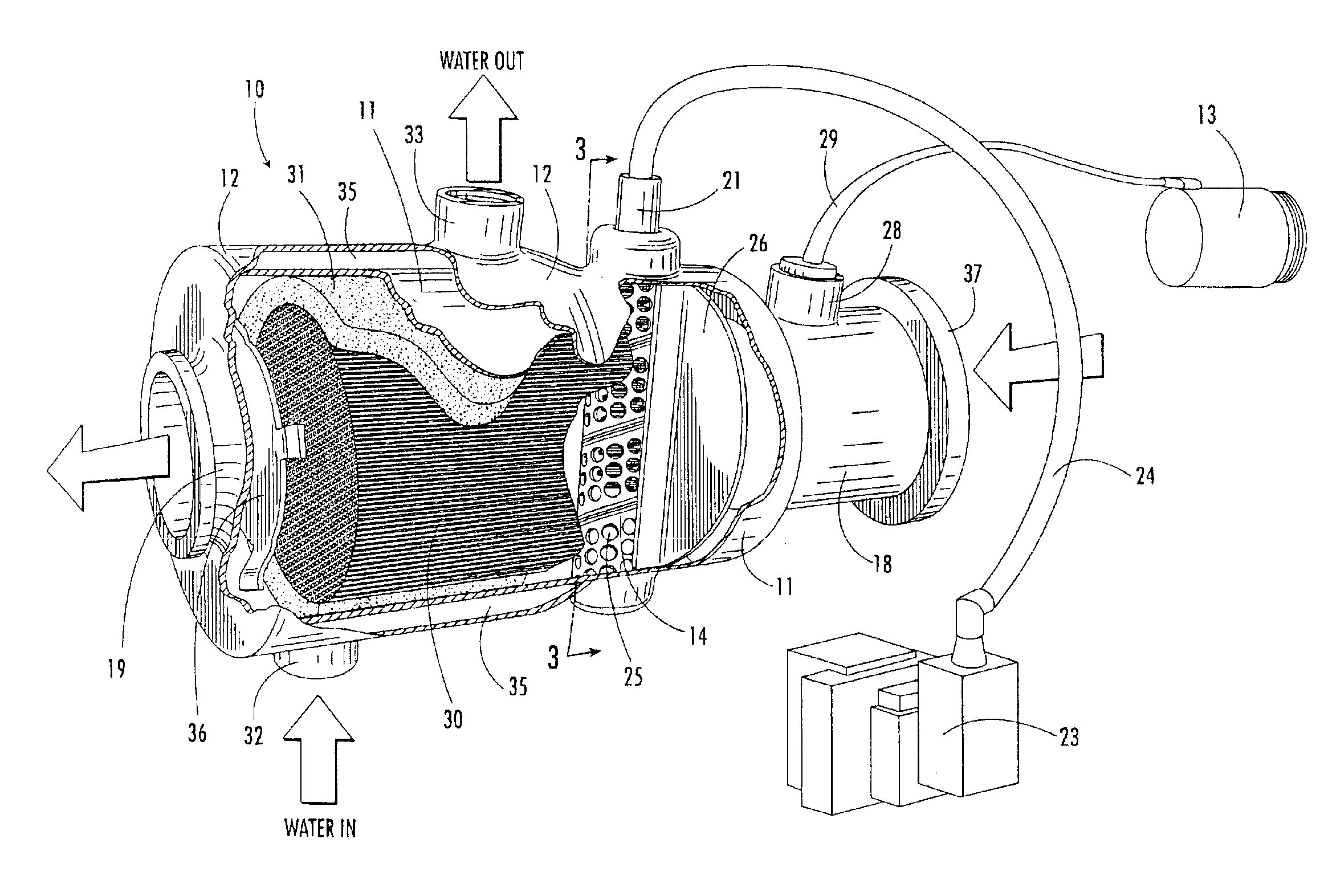
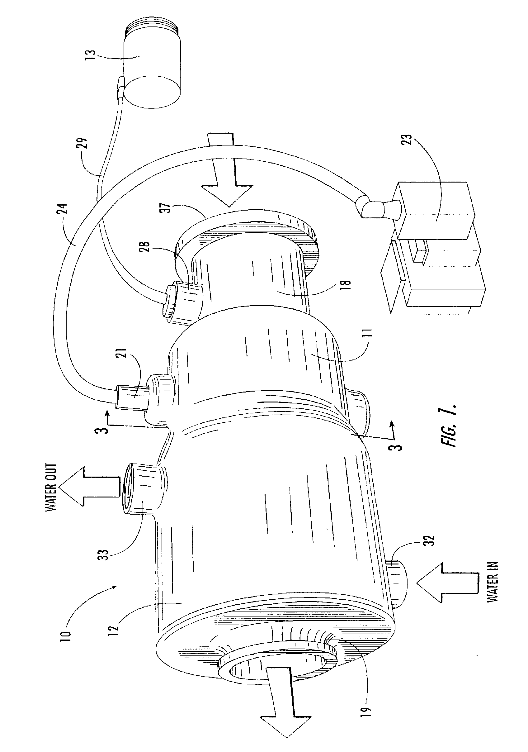
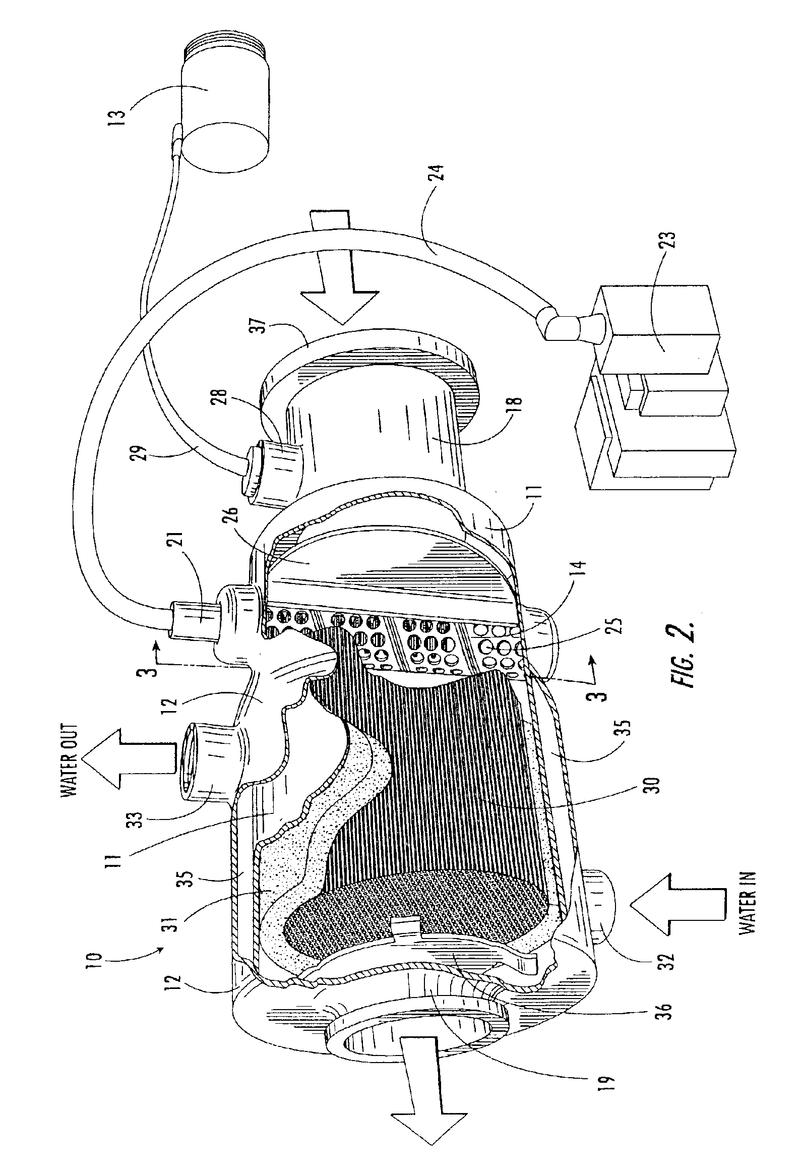
Referring now specifically to the drawings, a preferred embodiment of the emission control apparatus according to the present invention is illustrated in FIG. 1, and shown generally at reference numeral 10. As can be seen in FIG. 2, the emission control apparatus 10 comprises a treatment chamber 11 positioned within a manifold 12, and an air pump 13. A metal tube 14 containing an electrode 15, and a porous chemical substrate 16 are positioned within the treatment chamber 11 to promote a chemical reaction that reduces the concentration of pollutants in the gaseous emissions of a conventional marine electric generator engine 17, shown in FIG. 8.

As shown in FIG. 1, the treatment chamber 11 is a hollow cylinder, preferably made of 316 L stainless steel. The treatment chamber 11 includes an intake pipe 18 and an exhaust pipe 19 located at opposite lateral ends of the treatment chamber 11 that define openings through which a stream of gaseous emissions enters and exits the treatment chamb...


PUM


Abstract

An apparatus for reducing pollutants in internal combustion engine emissions, particularly marine electric generator engines, includes a treatment chamber having an intake opening for receiving gaseous emissions from the engine, and an exhaust opening for exiting emissions. A perforated metal tube is disposed within the treatment chamber, and an electrode is disposed within the metal tube in spaced apart relation to the metal tube. The electrode is encircled by the metal tube so that, upon applying a voltage at a predetermined frequency to the electrode, an arc is generated across the space between the electrode and the metal tube to promote a chemical reaction reducing the concentration of pollutants. The treatment chamber is contained within a manifold, and cooled by a flow of water. A supplemental air source is connected to the treatment chamber, and a chemical substrate is disposed within the treatment chamber for promoting the chemical reaction.

Description

The invention relates to an apparatus for reducing the concentration of pollutants in the exhaust emissions of an internal combustion engine, particularly an engine driving an electric generator on a boat. The invention is particularly adapted for connecting to the exhaust manifold of a marine electric generator engine.It is well known that internal combustion engines produce an exhaust emission containing pollutants that are harmful to the environment. Such pollutants include carbon monoxide, carbon dioxide and various hydrocarbons. There are many inventions for reducing the concentration of such pollutants in engine exhaust emissions. For example, U.S. Pat. Nos. 5,410,871 and 5,419,123 each disclose emission control devices particularly suited for reducing pollutant levels in automobile exhaust emissions.Pollution control for marine electric generator engines presents a unique set of challenges that have not been sufficiently addressed by the prior art. Houseboats and large cruise...

Claims


Application Information

Patent Timeline
Patent Type & Authority Patents(United States)
IPC IPC(8): B01D53/32B01D53/92F01N3/28F01N3/05F01N3/08F01N7/00F01N3/30
CPCB01D53/323B01D53/92F01N3/05F01N3/08F01N3/0892F01N3/2853F01N3/30F01N13/004F01N3/2828Y02T10/20F01N2590/02Y02T10/12
Inventor MILLS, MICHAELJAMES, DAVID
Owner ENVIROELEVATOR
Why Eureka
Try Eureka