
Planar NMR coils with localized field-generating and capacitive elements

a capacitive element and field-generating coil technology, applied in the field of rf probes, can solve the problems of limited resistance of these coil materials, limited sensitivity of conventional normal-metal coils, and only realizing the advantage, so as to minimize the chance of discharge

Inactive Publication Date: 2005-01-11
BRUKER BIOSPIN
View PDF12 Cites 26 Cited by
  • Summary
  • Abstract
  • Description
  • Claims
  • Application Information

AI Technical Summary

Benefits of technology

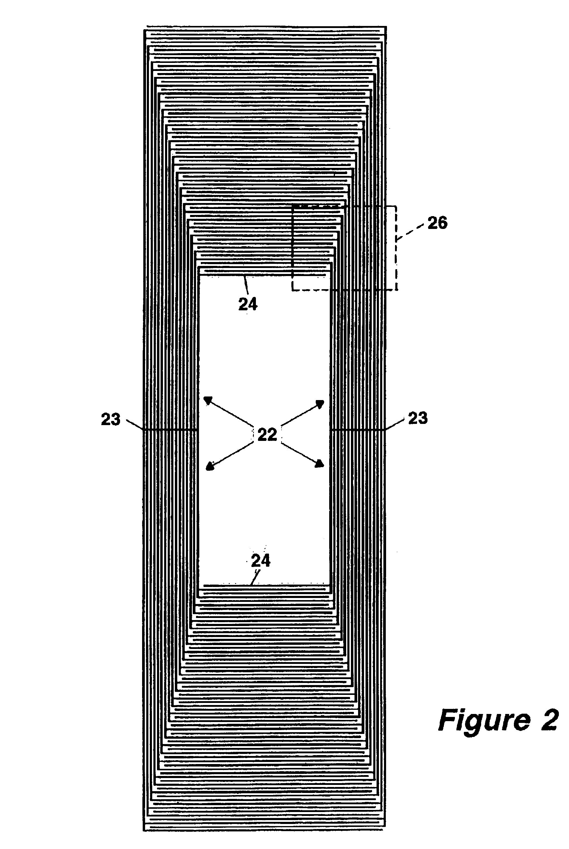
The connection between the magnetic field generating elements and the capacitor elements may vary. In one embodiment, each magnetic field generating element is connected to a plurality of capacitor elements, while in another embodiment, each capacitor element is connected to a plurality of magnetic field generating elements. The total number of capacitors formed by the loops may also vary from one embodiment to another, typically depending on the necessary resonant frequency. The capacitors are arranged in series with each other and with the magnetic field generating elements, and may total, for example, two or four. One embodiment, however, uses just a single capacitor formed by the capacitor elements. A variation of the present invention that is particularly useful for a one-capacitor coil makes use of sub-coils, each of which incorporates a plurality of the magnetic field generating elements and the interdigital capacitor elements. Preferably, the capacitor elements in such an embodiment would be located to both sides of the minor axis of the coil. This provides the coil with a good degree of symmetry. The location of capacitor elements may alternate between sub-coils, such that the capacitor elements of a first sub-coil are located to the opposite side of the oblong shape from the capacitor elements of any sub-coil immediately adjacent to it. Finally, it may be desirable to use isolated conductive segments within the resonator to occupy what would be otherwise unoccupied space. These isolated segments are not electrically connected to the current carrying loops, but serve to assist in the exclusion of RF magnetic fields from the coil.
In another embodiment of the invention, electrical discharge is controlled by using a dielectric cover that is located to the side of the conductive material opposite the planar substrate. The cover, together with the dielectric substrate, encloses the conductive material of the coil, thereby minimizing the chance of discharge. The cover may be fastened to the substrate with an adhesive, for example, a fluoropolymer film. The substrate and the cover may also be made of the same material, ensuring a thermal-expansion match and a dielectric breakdown field in the cover that is the same as that of the substrate. Although use of the cover may result in a lowering of the resonator frequency, it may be possible to compensate by trimming the coil, for example, with a laser.

Problems solved by technology

In each case, however, the resistance of these coil materials has limited their sensitivity.
However, even when cooled, the sensitivity of conventional normal-metal coils is still limited by their resistance.
However, this advantage can only be realized if the other factors necessary for a superior NMR probe are met, such as a reasonable filling factor and high RF and DC field homogeneity.
However, magnetic field disturbances by the coil can be a problem, and the current carrying capacity of the coil is somewhat limited.
Black discloses several embodiments, including split ring, solenoidal, saddle coils, birdcage coils and coils described as “Helmholtz pairs.” Black's embodiments are essentially conventional NMR coil designs and do not address the unique characteristics of high-temperature superconductor materials.
Unfortunately, this means that any magnetization of the coil material will affect the uniformity of the DC polarizing field (B0) over the sample volume, producing a distortion of the spectral line shape and degradation of SNR.
Because superconductors are strongly diamagnetic, line-shape distortions could be severe.
Thin-film HTS coils offer design and processing challenges not present with normal-metal coils.
Such orientation is extremely difficult to achieve on a nonplanar substrate.
This makes the achievement of a high filling factor more challenging.
Even when HTS films are deposited epitaxially on a planar substrate, crystalline defects inevitably occur.
This can lead to burn out of fine features of a coil exposed to high currents.
Third, it is well known in the art that forming ohmic contacts between an HTS and a normal metal is difficult and generally leads to parasitic losses at the point of contact.

Method used


Image

  • Planar NMR coils with localized field-generating and capacitive elements
  • Planar NMR coils with localized field-generating and capacitive elements
  • Planar NMR coils with localized field-generating and capacitive elements

Examples


second embodiment

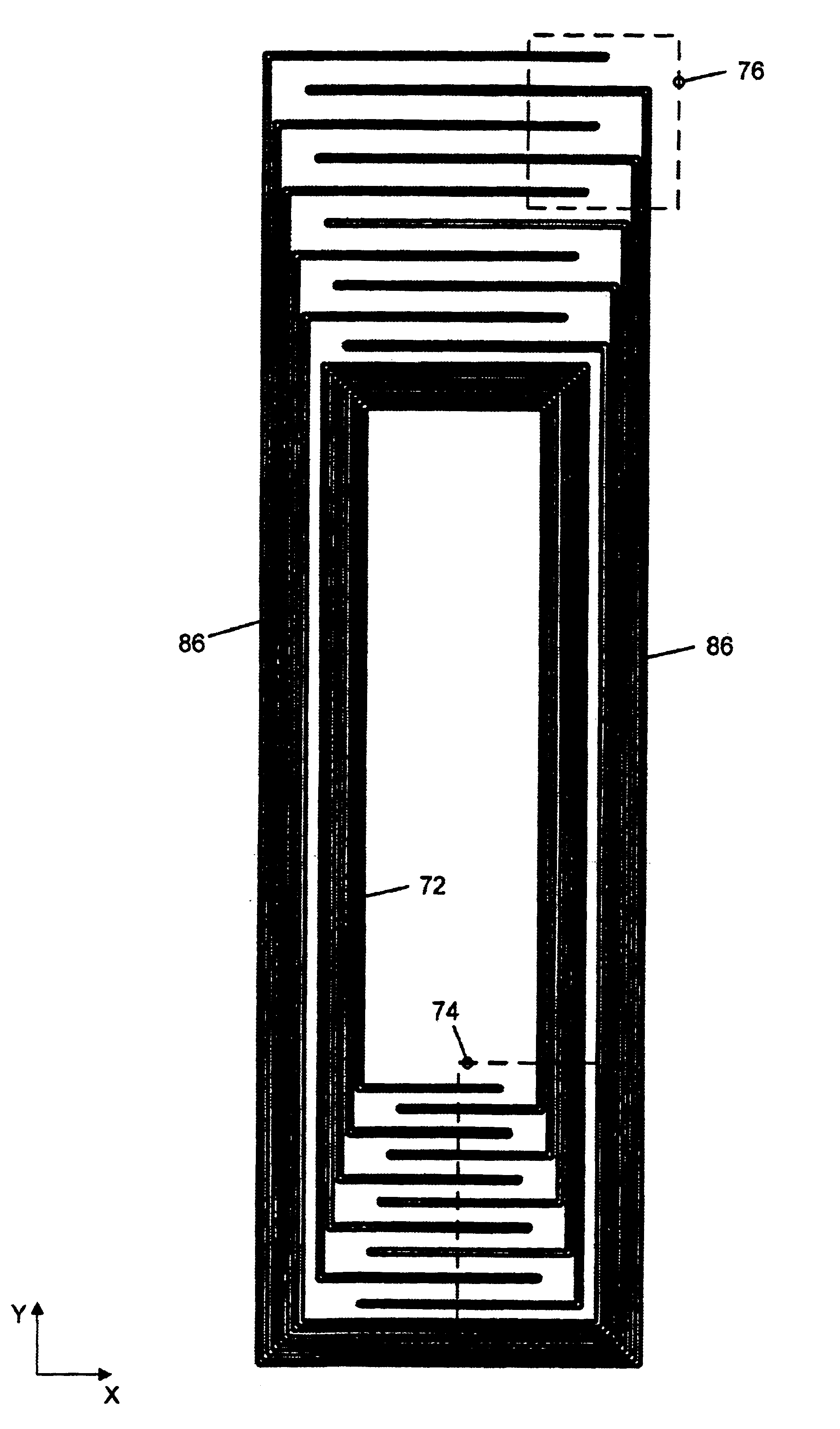
the present invention is shown in FIGS. 3 and 3A. As with FIGS. 2 and 2A, for illustrative purposes, FIGS. 3 and 3A show many fewer conductors than exist in the actual coil. The coil of this embodiment has four capacitors in series, two above the active sample volume and two below. A coil with this configuration may be useful, for example, to excite and detect 1H nuclei at 600.13 MHz in a 3-mm tube in a 14.1-Tesla magnet. A coil for detecting 1H (sometimes referred to as a “proton” coil) is often the innermost coil in a probe, since proton detection is quite often considered the most important. Since the resonant frequency necessary for proton detection is significantly higher than that for almost all other isotopes, particular design constraints on the coil exist. Because the necessary resonant frequency is higher, the total capacitance may be lower. This, in turn, allows the use of more capacitors and, as shown in FIG. 3, the example coil has four capacitors in series.

The voltage ...


PUM


Abstract

Improved superconducting coils for a nuclear magnetic resonance probe use capacitive elements that are located in regions further from an active sample volume than magnetic field generating elements to which they are electrically connected. The sample volume is a substantially oblong shape, and the magnetic field generating elements run substantially parallel to the major axis of the shape, while the capacitor elements run perpendicular to the major axis. Gaps between the capacitor elements, and the width of the elements themselves, may increase toward the outside of the coil to minimize electrical discharge. The variation may be according to a monotonic, possibly linear, function. Discharge may also be minimized by using a dielectric cover that, together with a coil substrate, encloses the coil.

Description

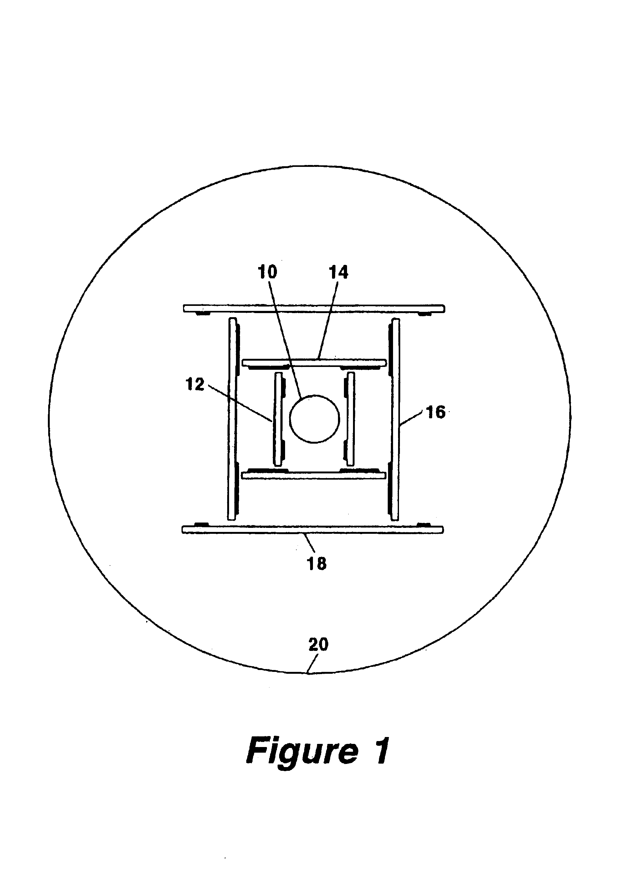
BACKGROUND OF THE INVENTION1. Field of the InventionThis invention relates to RF probes for nuclear magnetic resonance (NMR) spectroscopy and microscopy and, more particularly, to resonant coils for the transmission and reception of NMR signals.2. Description of Related ArtIn an NMR spectrometer probe, a sample is placed in a static magnetic field which causes atomic nuclei within the sample to align in the direction of the field. Transmit and receive coils, which may be combined in a single coil or set of coils, are placed in the probe positioned close to the sample. The transmit coils apply an RF magnetic field orthogonal to the direction of the static magnetic field, perturbing the alignment of the nuclei. The transmit signal is then turned off, and the resonant RF signal of the sample is detected by the receiver coil. The sensitivity of the spectrometer depends on a number of factors, including the strength of the static field, the closeness of the coupling between the RF coils ...

Claims


Application Information

Patent Timeline
IPC IPC(8): G01R33/34G01R33/32H01F5/00H01F6/00
CPCG01R33/341G01R33/34061G01R33/34007G01R33/34023G01R33/34092
Inventor WITHERS, RICHARD S.NAST, ROBERT E.
Owner BRUKER BIOSPIN
Learn More