
Optical member and method of producing the same, and projection aligner

a technology of optical members and projection aligners, which is applied in the field of optical members, can solve the problems of adverse influences, insufficiency of throughput of the entire optical system, and accumulation of transmission losses on the whole optical system, so as to improve the throughput of the optical system, enhance imaging performance, and improve the effect of optical system throughpu

Inactive Publication Date: 2005-02-01
NIKON CORP
View PDF17 Cites 6 Cited by
  • Summary
  • Abstract
  • Description
  • Claims
  • Application Information

AI Technical Summary

Benefits of technology

The present invention provides an optical member for photolithography that has high optical characteristics with respect to light with a wavelength of not more than 250 nm, even in the presence of scattering bodies. The optical member has a relatively long optical path length and is made of a fluoride crystal. By satisfying certain conditions, the optical member can maintain high internal transmittance and durability with respect to laser beams. The invention also provides a method of manufacturing the optical member and a projection exposure system using the optical member. The optical member is costly, but the invention provides a way to enhance its yield and increase its diameter upon carving out of the fluoride crystal.

Problems solved by technology

Here, even if an amount of transmission loss (an amount of loss by scattering+an amount of loss by absorption) of a lens is minute, accumulation of such transmission losses on the whole optical system largely affects the optical performance of the system.
Accordingly, in the case of a system composed of numerous optical members (lenses) such as an optical system used for photolithography, even if an optical member sufficient in the characteristic such as durability of transmittance with respect to a laser, an amount of birefringence or homogeneity in refractive index, there are possibilities of adverse influences such as insufficiency in throughput of the entire optical system, deterioration in contrast, occurrence of flares and ghosts, or the like.

Method used


Image

  • Optical member and method of producing the same, and projection aligner
  • Optical member and method of producing the same, and projection aligner
  • Optical member and method of producing the same, and projection aligner

Examples


example 1

(Fabrication of Optical Member)

Impurity elements such as metal were removed to the utmost from 50 kg of calcium fluoride powder (average grain size: 40 μm, a proportion of grains having sizes no smaller than 0.5 times and no larger than 1.5 times of the average grain size: 57%, concentrations of impurities: Cl<0.1 ppm, Br<0.1 ppm, I<0.1 ppm, Co<0.05 ppm, Ce<0.05 ppm, La<0.05 ppm, Y<0.05 ppm, Mn<0.1 ppm, Cu<0.1 ppm, Ni<0.1 ppm, K<0.1 ppm, Cr<0.1 ppm, Li<0.2 ppm, Na <0.2 ppm, Pb<0.5 ppm, Fe<0.5 ppm, Ba<1.0 ppm, Sr<20 ppm). 1.6 kg of lead fluoride (about 1 mol %) was added as a scavenger thereto and agitation was satisfactorily performed. The mixture was put into a crucible made of carbon, which was held in a clean condition by rinsing with calcium fluoride powder. Then the crucible was introduced into a pre-processing apparatus which was cleaned and held in a clean condition. After the inside of ...

example 2

1.6 kg of lead fluoride (about 1 mol %) was added as a scavenger to 50 kg of calcium fluoride powder similar to example 1 and agitation was satisfactorily performed. The mixture was put into a crucible made of carbon, which was held in a clean condition by rinsing with calcium fluoride powder. Then the crucible was introduced into a pre-processing apparatus which was cleaned and held in a clean condition. Here, the above-mentioned operations were performed inside a clean room of class 10,000 in order to avoid interfusion of impurity elements or dust in the event of mixing and agitation and in the event of filling the raw material.

After the inside of the apparatus was pumped out to vacuum, the temperature was maintained at 300° C. for a given time period, whereby impurities such as water or carbon dioxide were removed by evaporation. Next, the temperature was increased slowly so as to promote a sufficient reaction between the calcium fluoride powder and the scavenger. The calcium flu...

example 3

Among the lenses constituting the projection optical system shown in FIG. 5, the optical member of example 1 was applied to six lenses L45, L46, L63, L65, L66 and L67, and lenses made of fused silica (internal transmittance including loss by scattering: about 99.8%) were applied to the rest of the lenses. Accordingly, a projection exposure system shown in FIG. 4 was fabricated.

As a result of evaluation of an imaging performance of this projection exposure system, desired throughput (135 sheets / hr) was achieved in the case of φ200-mm wafers. Moreover, flares and ghosts observed therein accounted for about 1% as light noises, which were almost ignorable in practical use.


PUM

PropertyMeasurementUnit
diameteraaaaaaaaaa
diameter dmaxaaaaaaaaaa
diameteraaaaaaaaaa

Abstract

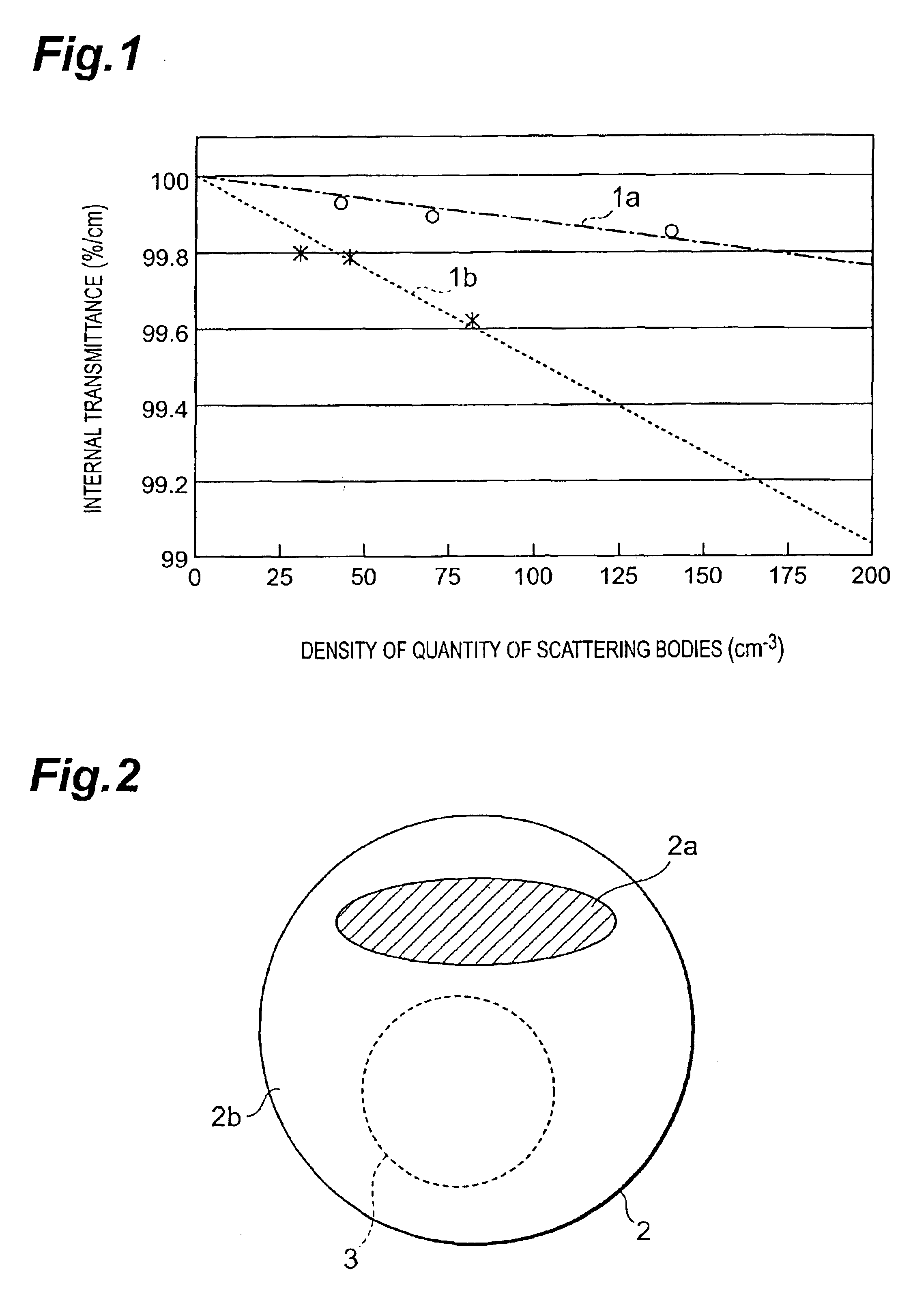
An optical member of the invention is an optical member for photolithography used together with light having a wavelength of not more than 250 nm. The optical member is made of a fluoride crystal in which a maximum diameter dmax (cm) of scattering bodies existing internally and a quantity ns of the scattering bodies per 1 cm<3 >satisfy a condition represented by following formula (1):

Description

FIELD OF THE INVENTIONThe present invention relates to optical members made of fluoride crystalline materials for use in ultraviolet and vacuum-ultraviolet regions with a wavelength of not more than 250 nm, a method of manufacturing the same, and projection exposure systems such as steppers or scanners which apply the optical members to optical systems.BACKGROUND ARTIn recent years, micro-fabrication technology on wafers has been requested along with development of higher integration and higher sophistication in VLSI (very large scale integration), and photolithographic technology has been widely used as a fabrication method therein. It is desirable that a projection lens of a projection exposure system, which is a key to the photolithographic technology, possesses high imaging performances (resolution and focal depth).The resolution and the focal depth depend on a wavelength of light and on an NA (numerical aperture) of a lens which are used upon exposure. When an exposure waveleng...

Claims


Application Information

Patent Timeline
Patent Type & Authority Patents(United States)
IPC IPC(8): G02B1/00G02B1/02G03F7/20
CPCC30B11/00C30B29/12G03F7/70958G03F7/70216G02B1/02
Inventor OBARA, HIDEKIENDO, KAZUMASA
Owner NIKON CORP
Learn More