
Single frequency laser source for optical data storage system

a single-frequency laser and data storage technology, applied in the field of single-frequency laser sources and optical fibers in optical data storage systems, can solve the problems of limiting the spacing between magneto-optical disks, slow speed at which prior art magneto-optical heads are mechanically moved to access new data tracks, and large prior art magneto-optical heads. the effect of noise reduction

Inactive Publication Date: 2005-02-01
SEAGATE TECH LLC
View PDF67 Cites 17 Cited by
  • Summary
  • Abstract
  • Description
  • Claims
  • Application Information

AI Technical Summary

Benefits of technology

The present invention provides improvements over prior art optical disk drives. The improvements allow an increase in the number of storage disks that can be placed within any given volume. The improvements include the use of optical fibers to transfer information to and from optical storage media. The optical disk drive further includes a high resonance frequency tracking servo device on a reduced profile head which in conjunction with the optical fibers provides Improved access to storage media, improved disk drive access times, and improved data transfer rates.
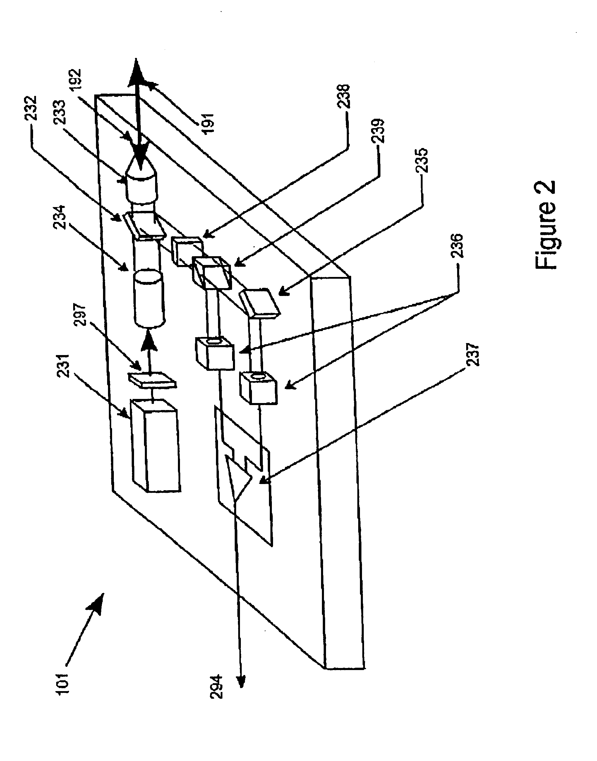
In the preferred embodiment, the information is transferred to and from magneto-optical storage disks using optical fibers that are single-mode polarization maintaining optical fibers. Due to inherent birefringence of single-mode polarization maintaining optical fibers, the present invention identifies that by using single frequency laser source (ie., a distributed feedback (DFB) laser diodes,) a polarization state conveyed by the polarization maintaining optical fibers may be conveyed with significantly reduced noise over that when used with conventional Fabry-Perot diode lasers.

Problems solved by technology

Conventional magneto-optical heads, while presently providing access to magneto-optical disks with areal densities on the order of 1 Gigabit / in2, tend to be based on relatively large optical assemblies which make the physical size and mass of the head rather bulky (typically 3-15 mm in a dimension).
Consequently, the speed at which prior art magneto-optical heads are mechanically moved to access new data tracks on a magneto-optical storage disk is slow.
Additionally, the physical size of the prior art magneto-optical heads limits the spacing between magneto-optical disks.
Because the volume available in standard height disk drives is limited, magneto-optical disk drives have, thus, not been available as high capacity commercial products.
While the static optics described by Yamada provides access to both surfaces of a plurality of phase-change optical disks contained within a fixed volume, Yamada is limited by the size and mass of the optics.
Consequently, the performance and the number of optical disks that can be manufactured to function within a given volume is also limited.

Method used


Image

  • Single frequency laser source for optical data storage system
  • Single frequency laser source for optical data storage system
  • Single frequency laser source for optical data storage system

Examples


Embodiment Construction

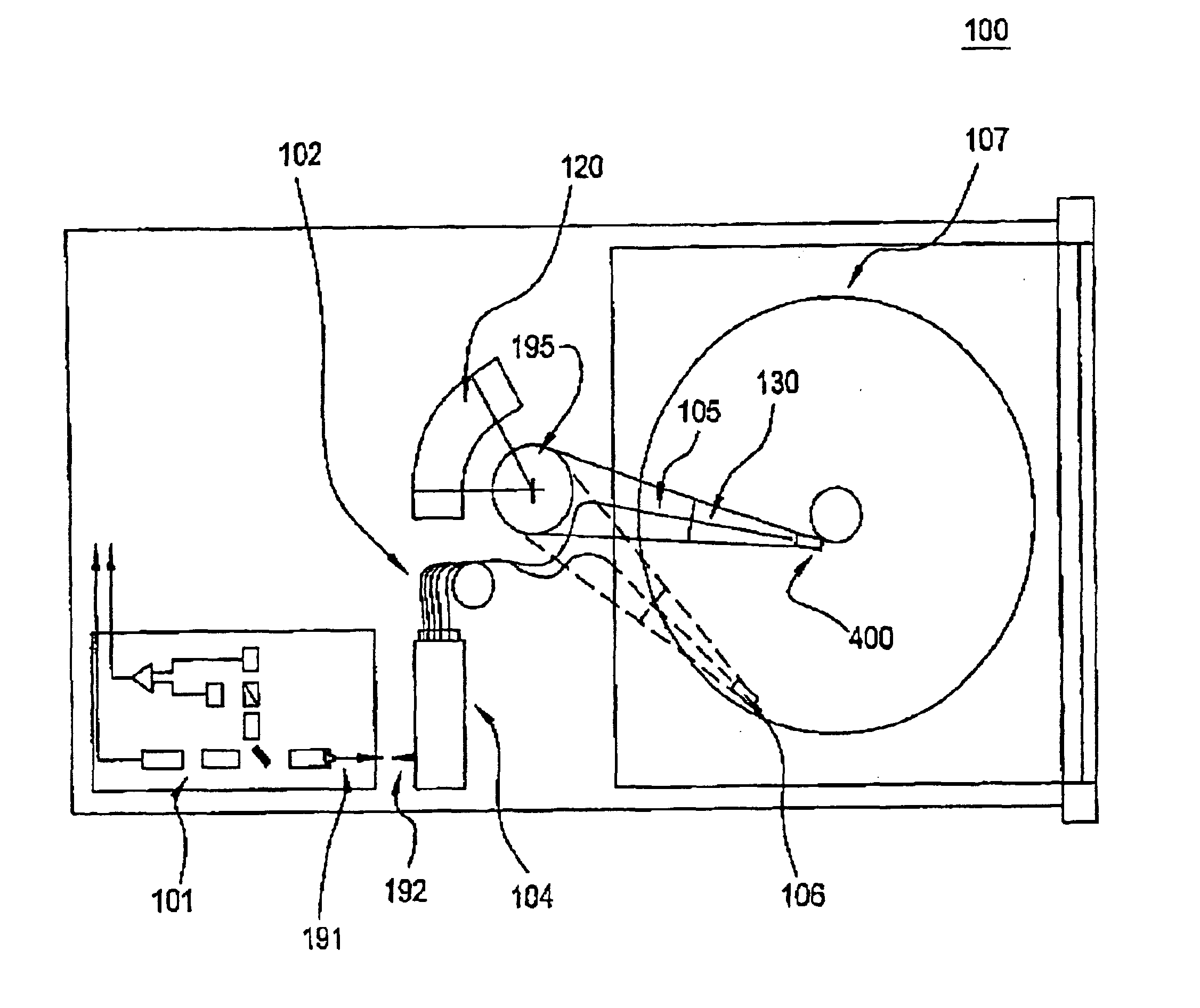
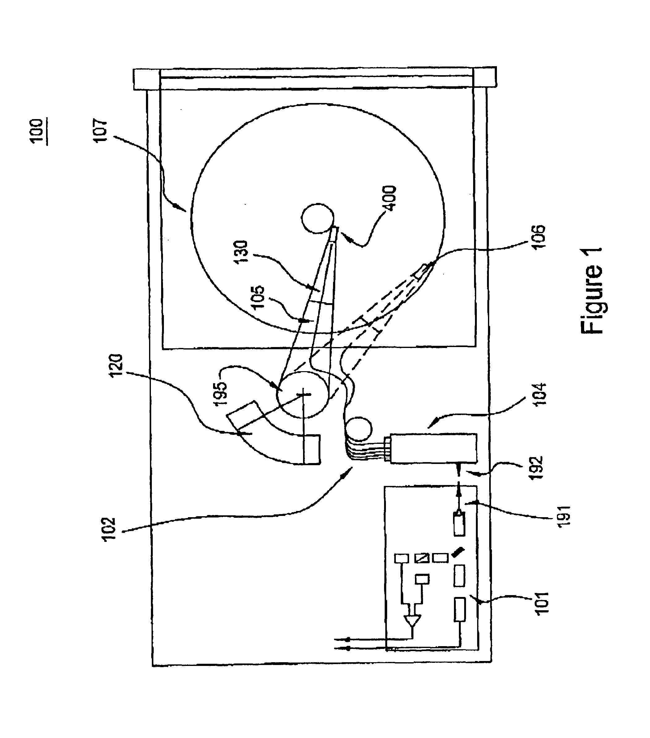
Referring in detail now to the drawings wherein similar parts of the invention are identified by like reference numerals, there is seen in FIG. 1 a magneto-optical storage and retrieval system 100. In a preferred embodiment, the magneto-optical (MO) data storage and retrieval system 100 includes a set of Winchester-type flying heads 106 that are adapted for use with a set of double-sided first surface MO disks 107 (one flying head for each MO disk surface). The set of flying heads 106 (hereinafter referred to as flying MO heads) are coupled to a rotary actuator magnet and coil assembly 120 by a respective suspension 130 and actuator arm 105 so as to be positioned over the surfaces of the set of MO disks 107. In operation, the set of MO disks 107 are rotated by a spindle motor 195 so as to generate aerodynamic lift forces between the set of flying MO heads 106 and so as to maintain the set of flying MO heads 106 in a flying condition approximately 15 micro-inches above the upper and ...


PUM

PropertyMeasurementUnit
wavelengthaaaaaaaaaa
sizeaaaaaaaaaa

Abstract

An optical data storage system utilizes optical fibers for transfer of information to and from storage media. The storage media includes magneto-optical storage disks. The optical fibers are single-mode polarization maintaining optical fibers. A single frequency laser diode provides a source of polarized light. Accordingly, a polarization state conveyed by the polarization maintaining optical fiber is accurately reproduced with reduced noise, as compared to use of a Fabry-Perot laser diode.

Description

BACKGROUND OF THE INVENTION1. Field of the InventionThe present invention relates generally to laser sources used in data storage systems. More particularly, the present invention relates to the use of single-frequency laser sources and-optical fibers-in optical data storage systems.2. Background ArtIn a magneto-optical storage system, using a magneto-optical (MO) recording material deposited on a rotating disk, information may be recorded on the disk as spatial variations of magnetic domains. During readout, a magnetic domain pattern modulates an optical polarization, and a detection system converts a resulting signal from optical to electronic formatIn one type of a magneto-optical storage system, a magneto-optical head assembly Is located on a linear actuator that moves the head along a radial direction of the disk to position the optical head assembly over data tracks during recording and readout A magnetic coil is placed on a separate assembly on the head assembly to create a m...

Claims


Application Information

Patent Timeline
Patent Type & Authority Patents(United States)
IPC IPC(8): G02B26/08G02B6/35G02B6/42G02B6/126G11B11/105G11B7/22G11B11/00G11B7/125G11B7/085G11B7/12G11B7/135H02N1/00H04B10/135G02B6/10G11B7/0037G11B7/09G11B7/14G11B7/00
CPCB81B3/0051H04B10/2572G02B6/126G02B6/3512G02B6/3518G02B6/4246G02B26/0833G02B26/0841G02B26/085G02B26/0866G11B7/08564G11B7/1203G11B7/122G11B7/127G11B7/1362G11B7/1365G11B7/1372G11B7/1384G11B7/22G11B11/10532G11B11/10534G11B11/10541G11B11/10543G11B11/1058G11B11/10595H02N1/008G02B6/3548G02B6/357G02B6/3584G11B7/0037G11B7/08576G11B7/0901G11B7/14G11B11/10515G11B11/10554G11B11/10563G11B11/10569G02B6/105
Inventor HEANUE, JOHN F.HURST, JR., JERRY E.WILDE, JEFFREY P.
Owner SEAGATE TECH LLC
Learn More