

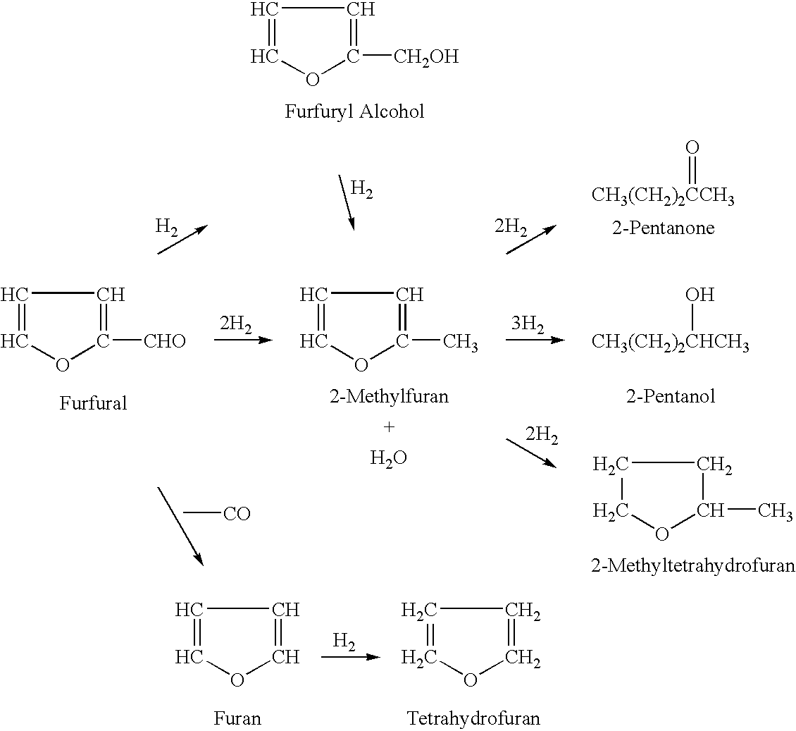
Processes for the preparation of 2-methylfuran and 2-methyltetrahydrofuran
a technology of 2-methylfuran and tetrahydrofuran, which is applied in the field of processes for the preparation of 2methylfuran and 2methyltetrahydrofuran, can solve the problems of inconsistent yield or purity of the products formed, not easy to scale up, and no literature found for the successful use of liquid-phase hydrogenation process to produce 2-mthf. , to achieve the effect of efficient production, low cost and efficient production
- Summary
- Abstract
- Description
- Claims
- Application Information
AI Technical Summary
Benefits of technology
Problems solved by technology
Method used
Image

Examples
example 1
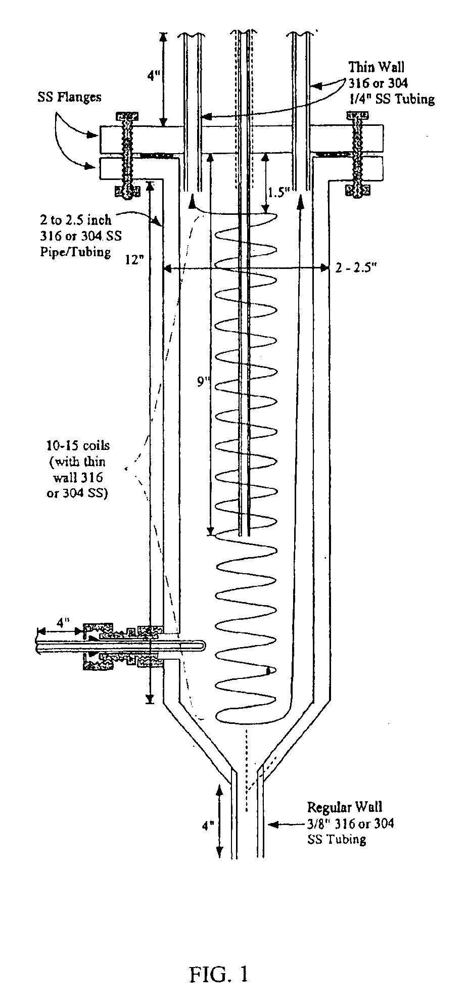
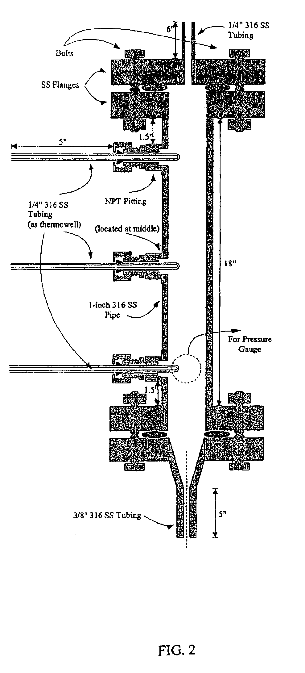
A vapor-phase, catalytic hydrogenation of furfural was conducted at atmospheric pressure using a vaporizer and reactor as described herein. The design of the vaporizer used for the vapor-phase, catalytic hydrogenation of furfural is shown in the schematic diagram as shown in FIG. 1.
The vaporizer had a vertical design with a feed line extending through the top of the vaporizer. The hydrogen gas was delivered through tubes extending through the top of the vaporizer. The temperature of the feed line was maintained by circulating heating oil inside coils positioned around the feed line within the vaporizer to improve the efficiency of vaporizing the feedstock. The feed line was placed to deliver the furfural-containing feedstock into the center of the vaporizer chamber. A thermowell near the bottom of the vaporizer contained a thermocouple used for temperature measurement. The lower portion of the vaporizer had a tapered design that reduced holdup inside the vaporizer and improved the c...
example 2
A vapor-phase, catalytic hydrogenation of 2-MF was conducted at atmospheric pressure using a vaporizer and reactor as described in Example 1. A nickel-based catalyst obtained from United Catalysts, Inc., Louisville, Ky. and identified as product number C46-07-3 RS was used for the vapor-phase hydrogenation. The C46-07-3 RS catalyst had a surface area of 138.2 square meters per gram, a pore volume of 0.5145 milliliters per gram and a compacted bulk density of 45.1 pounds per square foot. The weight-time for the vapor-phase, catalytic vapor-phase hydrogenation was determined to be 7.74×10⁴ grams catalyst-minutes per liter. Weight-time was herein defined as the ratio of the mass of catalyst to the volumetric flow rate of the vaporized feedstock (for example, furfural or 2-methylfuran) mixed with hydrogen gas.
The 2-MF used was obtained from Great Lakes Chemical Corporation, Memphis, Tenn. It was vaporized and mixed with hydrogen within the vaporizer. The hydrogen was delivered into the ...
example 3
A vapor-phase, catalytic hydrogenation of 2-MF was conducted using the same set-up as described in Example 2 above, except that the hydrogenation temperature and 2-MF flow rate were modified. The reaction was conducted while maintaining the 2-MF flow rate at about 1.0 ml / min and varying the hydrogenation temperature from about 100° C. to about 130° C. These modified reaction conditions resulted in the percentage of 2-MTHF increasing to almost 90 percent and the percentage of unreacted 2-MF decreasing insignificant amounts (less than one percent).
PUM
 Abstract
Description
Claims
Application Information