
Building panel and plant for the manufacture thereof

a technology for building panels and plants, applied in the direction of building components, bulkheads/piles, artificial islands, etc., can solve the problems of difficult to form intimate bonds, unreliable attachment, and delicate operation, and achieve simple and fast manufacturing, accurate positioning, and easy production

Inactive Publication Date: 2005-02-22
PELLICER CARLOS FRADERA
View PDF21 Cites 39 Cited by
  • Summary
  • Abstract
  • Description
  • Claims
  • Application Information

AI Technical Summary

Benefits of technology

In view of the foregoing, it would be desirable to have a building panel fulfilling the largest number of the following conditions:1. have unbeatable conditions of adhesion of the patterned layer to the material of the resistant body.2. be provided with reinforcement means which allow it to be attached to a lattice support structure, are easy to produce, may be accurately located and are completely reliable under extreme conditions.3. coordinate the attachment thereof to the lattice support structure with the attachment of inside wall internal slabs.4. comprise a buttstrap arrangement hiding the joints between panels having an architectural pattern.5. be simple and speedy to manufacture with high quality in a plant which is economical in equipment and labor.

Problems solved by technology

Such building panels have drawbacks such as, in principle, the difficulty of forming an intimate bond between the synthetic resin layer, forming the visible surfaces of the panel and the resistant body material, particularly when this material consists of an air-setting hydraulic material, such as a cement or lime mortar, concrete, plaster and the like.
While the foregoing solution is generally sufficient for its task, it is delicate to carry out since it depends on many factors which are hard to control in industrial production to the extent that, under extreme environmental conditions, the patterned layer may separate from the resistant material body.
Also, a further drawback detected in the panels disclosed in the aforementioned Spanish Utility Model 9900014 is that the means provided for attaching the panel to a support structure are internal to the panel and are complex, artificious and hard to use, providing for unreliable attachment, which is quite unacceptable in a building, where these support structures are of lattice type formed essentially by metal upright sections which are connected by horizontal metal cross-member sections, with the ensemble being stabilized by strutting.
All these systems suffer from the drawback that they are complex, require scaffolding and shuttering in the majority of cases, require specialized labor and are not absolutely reliable in situations of movement of the structure due to settling thereof, to the action of gale force winds, earthquakes, explosions, etc.
Furthermore, when prefabricated panels reproducing architectural type patterns on the visible face thereof, such as stone masonry, brickwork, carvings or other designs, are set side-by-side, the joints formed longitudinally and transversally therein are extremely obvious, breaking the aesthetics of the pattern design.
This arrangement reveals the imitation, which is unaesthetic and impossible to hide with putties and the like.
This is a limitation for the use of such facade panels imitating brickwork.
The same happens with facade panels imitating natural stone masonry, in which case it is much more difficult to disguise the straight lines of the joints, since the joints between the stones are very irregular and in no case are they straight.
This assembly system has the drawback that the movements due to settling of the structure, to the effects of wind, to snow loads, to seismic movements, structural vibrations, explosions or others cause relative movements between the members of the lattice structure and the facade panels, causing deterioration of said internal slabs by the sawing action caused therein by the ensemble attachment screws, which changes the distance between the lattice structure and the facade panels.
As a result, the drawback arises that such panels are placed in a swaying situation, leading not only to an aesthetic deterioration, but also to the risk of separation and, furthermore, the structure loses the strutting effect offered by said internal slabs.
These plants require large spaces to lay out the tracks, a high energy consumption to heat the tracks, moving means for placing and installing the reinforcement and other, also moving, means for pouring and vibrating the concrete, all of which means that such plants are extremely burdensome and hardly competitive, to which there should be added the enormous number of molds required for a profitable manufacturing operation.

Method used


Image

  • Building panel and plant for the manufacture thereof
  • Building panel and plant for the manufacture thereof
  • Building panel and plant for the manufacture thereof

Examples


Embodiment Construction

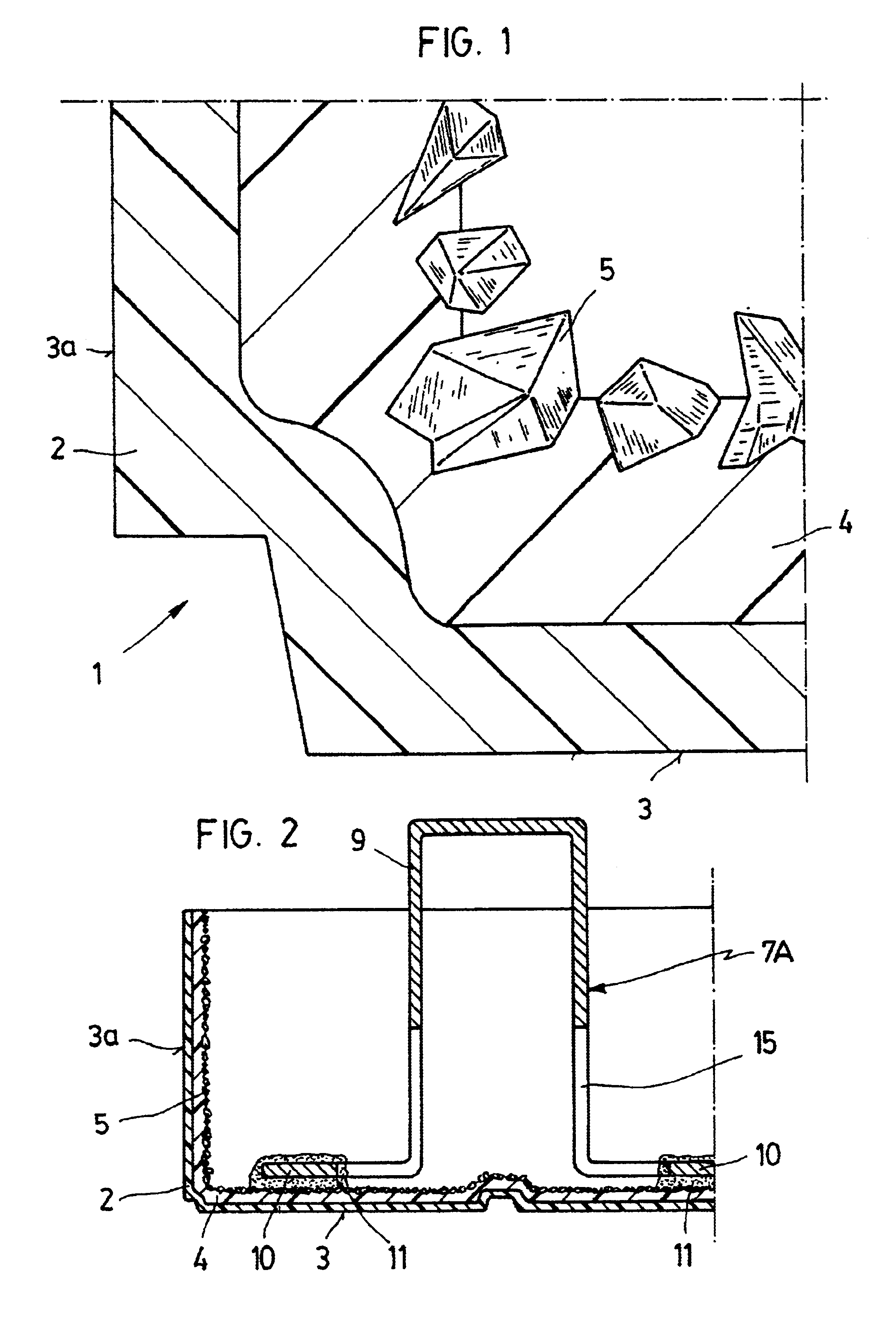
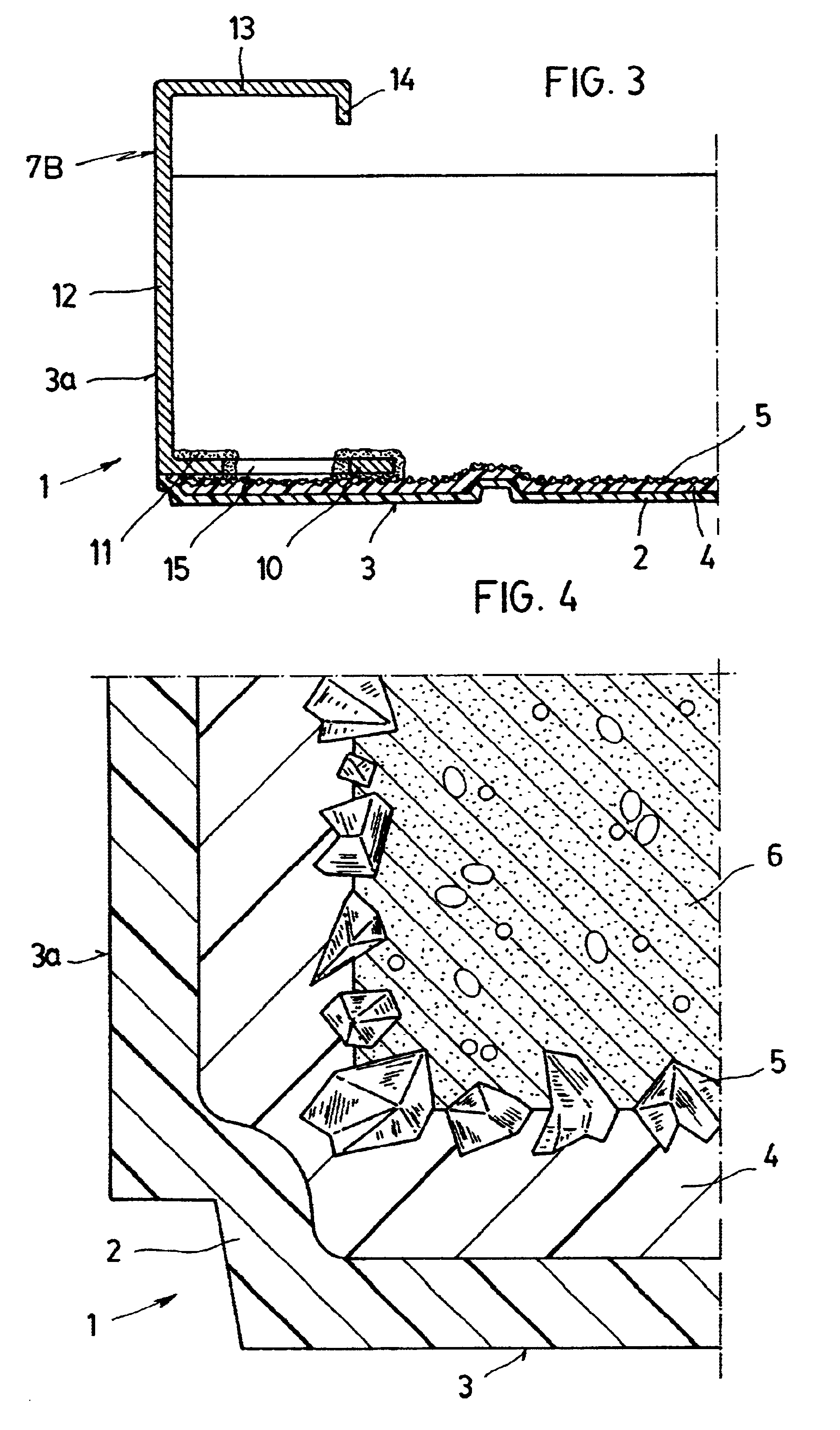
FIG. 1 shows a building panel 1 having, according to the invention, a structure constituted by a patterned layer 2 which, molded in synthetic resin, forms the patterned surface of the visible face 3 of the panel and constitutes a sort of shell for the panel 1 which comprises the edges 3a.

The said external layer 2 comprises, over the entire inner surface thereof, an inner layer 4, also of synthetic resin, having the entire free surface thereof covered with a solid bulk material 5. The components of this material are firmly embedded in part in said inner layer 4 and provide a substantial free surface area for anchoring the material of the resistant body 6 applied thereover, which material fills the entire volume of the said panel shell 1, at the same time as it includes therein reinforcement means 7, in general, which are provided with points directly accessible from the outside of the concealed face 8 of the panel 1, as may be seen in FIGS. 2, 3, 5, 6 and 9.

The solid bulk material 5...


PUM


Abstract

This building panel consists of lightweight panel for external or internal closures of latticework support structures, which is constituted by slabs of air-setting resistant material. The slabs are reinforced in the facade panels for external closures and unreinforced for the dividing panels for internal closures. They are provided with a patterned surface on the visible face and are smooth or shaped at the edges. The visible face is formed by a thin layer of molded synthetic resin or fine mortar paste. When the layer is molded synthetic resin and is disposed as a shell for the panel, it comprises over the whole of the inner surface thereof an internal synthetic resin layer, the entire free surface of which is covered with a solid bulk material, the components of which firmly partially anchored in said internal layer and afford a substantial free surface for anchorage of the air-setting material forming the resistant body poured thereover. This material fills the entire volume of said panel shell, at the same time as it includes therein reinforcement means provided with points directly accessible from the outside of the concealed face of the panel.

Description

FIELD OF THE INVENTIONThis invention relates to a building panel and to a plant for the manufacture thereof. To be precise, it relates to a lightweight panel for external or internal closures of latticework support structures, formed by uprights connected by horizontal crossmembers. The panel is formed by slabs of air-setting resistant material which are reinforced in the facade panels for external closures and unreinforced in the dividing panels for internal closures and which have a patterned surface on the visible face thereof and a smooth or shaped surface at the edges thereof. The surface is formed by a thin layer of a synthetic resin or a fine mortar paste. The layer is formed as a shell partially enveloping a body of air-setting resistant material on which it confers a quality finish of architectural type with essential properties of resistance to weathering and environmental pollution and is formed in molding arrangements constituted by a mold-holder having an engraved botto...

Claims


Application Information

Patent Timeline
IPC IPC(8): B28B19/00B28B15/00E04C2/04E04F13/08E04C2/26
CPCB28B15/00B28B19/00E04F13/083E04F13/0803E04F13/0862E04C2/04
Inventor PELLICER, CARLOS FRADERA
Owner PELLICER CARLOS FRADERA
Learn More