

In situ forming hydrogels
- Summary
- Abstract
- Description
- Claims
- Application Information
AI Technical Summary
Benefits of technology
Problems solved by technology
Method used
Image

Examples
example 1
Synthesis of End-Group Modified PEGs
Poly (ethylene glycol) (PEG) of nominal molecular weight 6000 g / mol (6K) (from Fluka), 10K (from Aldrich), and 20K (from Fluka) were used. Three different fluorinated alcohols (CnF2+1CH2CH2OH, where n=6, 8, 10) were purchased from Lancaster Synthesis Inc. Isophorone diisocyanate (IPDI), dibutyltin diacetate and anhydrous tetrahydrofuran (THF) were purchased from Aldrich.
The method of Glass et al. (Kaczmarski and Glass, Macromolecules, 26:5149-5156, 1993) was used to attach the perfluorinated end groups to the terminal hydroxyls of PEG. PEG was dried by azeotropic distillation in toluene, and was reacted with 100 fold molar excess (with respect to end-groups) of vacuum-distilled IPDI in anhydrous THF for 48 hours. This intermediate was precipitated in anhydrous ethyl ether to remove unreacted IPDI, and was subsequently reacted with a 10-fold excess of perfluoroalcohol in anhydrous THF for 48 hours. Dibutyltin diacetate was added for the second step...
example 2
Formation of Hydrogel Phases
The phase behavior of two-end modified PEGs was governed by the relative length of the PEG chain and the perfluorinated hydrocarbon end groups (Table 2). Some of the two-end modified PEGs showed phase separation and others did not. This phase separation phenomenon can provide useful applications for these transition systems; when this system is used as a delivery device in the open system, it will maintain the high modulus matrix of the equilibrium composition, compared to the systems using materials which do not show the phase separation, since the matrix formed from these would be dissolved with continuous lowering of the modulus for the same concentration of polymers.
Among the two-end modified PEGs synthesized, 6KC 10 did not exist as a homogeneous phase in water, rather only as a slightly swollen precipitate. At the other extreme, 20KC10 and 20KC8 existed as homogeneous solutions over the whole range of polymer concentrations, though the viscosity inc...
example 3
Rheological Properties of Gel Phases
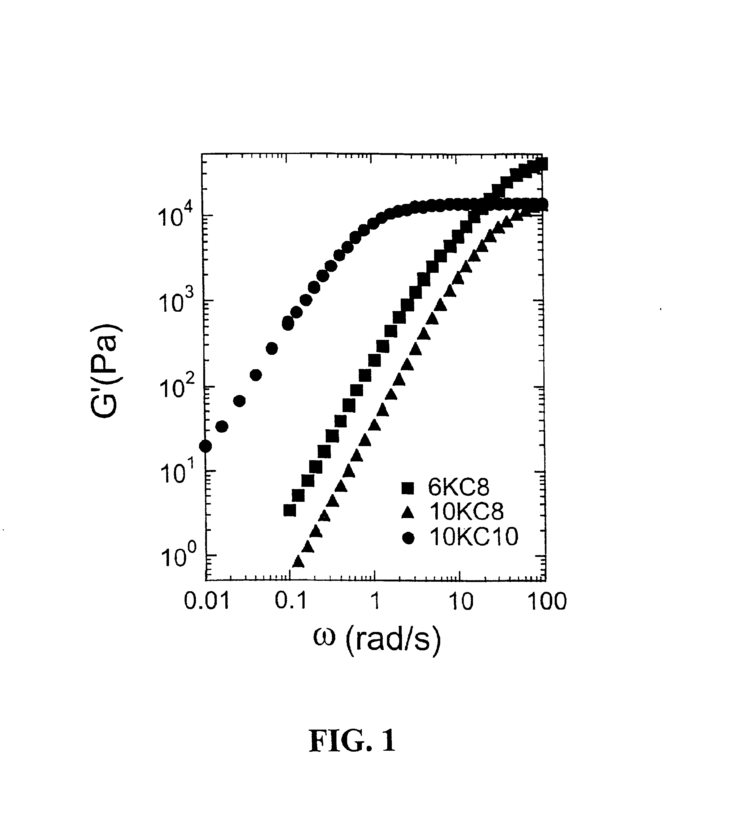
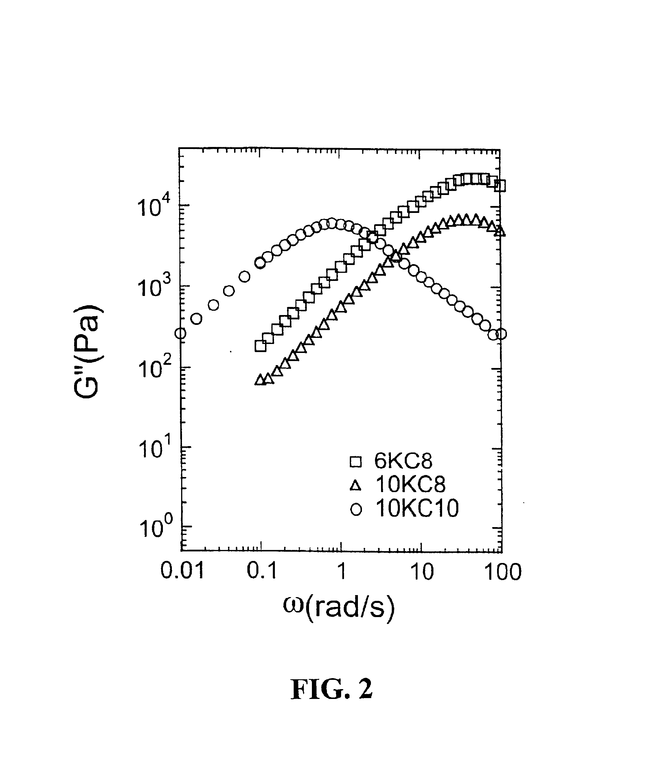
Rheological measurements were made to gain initial insight into gel structure (Table 3). Previous work by Annable, et al., (J. Rheology 37:695-726, 1993) showed that the PEG systems modified with hydrocarbon tails were governed by a single relaxation time. Thus, these systems can be well described by a simple Maxwell model.
The gel phases of all the systems showing phase separations were still governed by the single relaxation behavior. A similar order of magnitude of infinite modulus (G∝, 104 Pa) was observed for 10KC10 and 10KC8, indicating the similar density of physical junctions within these two gels, which coincide with similar values of swelling ratios. A higher value was observed for 6KC8, meaning a higher density of physical junctions was present, which also agrees with the smaller swelling ratio. The large difference in relaxation time between 10KC10 and 10KC8 showed that the addition of one CF2 unit significantly increases the strength o...
PUM
| Property | Measurement | Unit |
|---|---|---|
| Fraction | aaaaa | aaaaa |
| Fraction | aaaaa | aaaaa |
| Fraction | aaaaa | aaaaa |
Abstract
Description
Claims
Application Information