

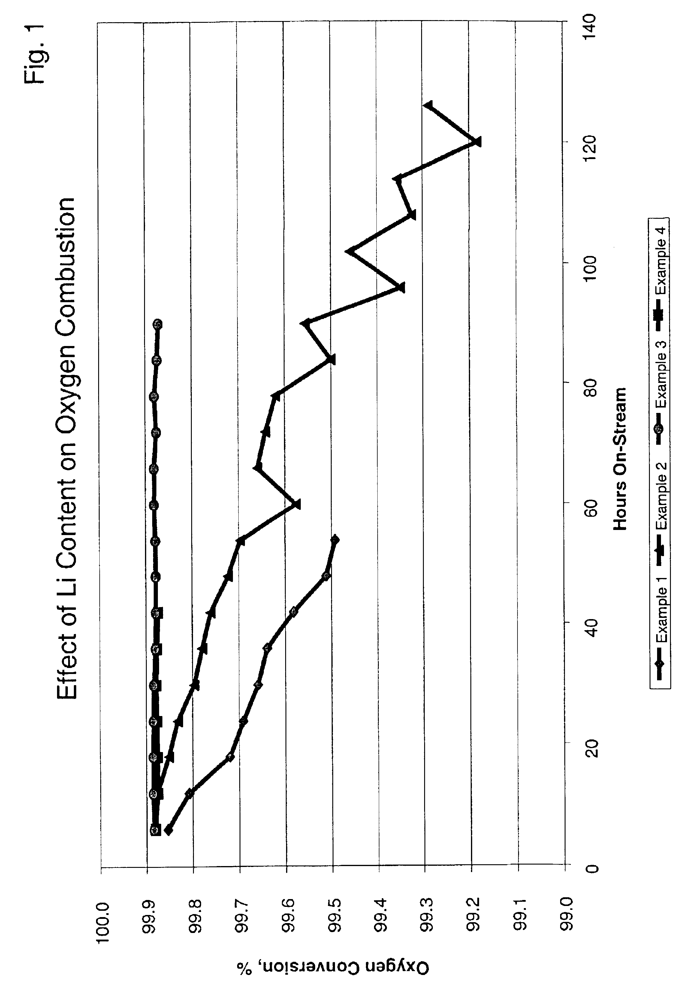
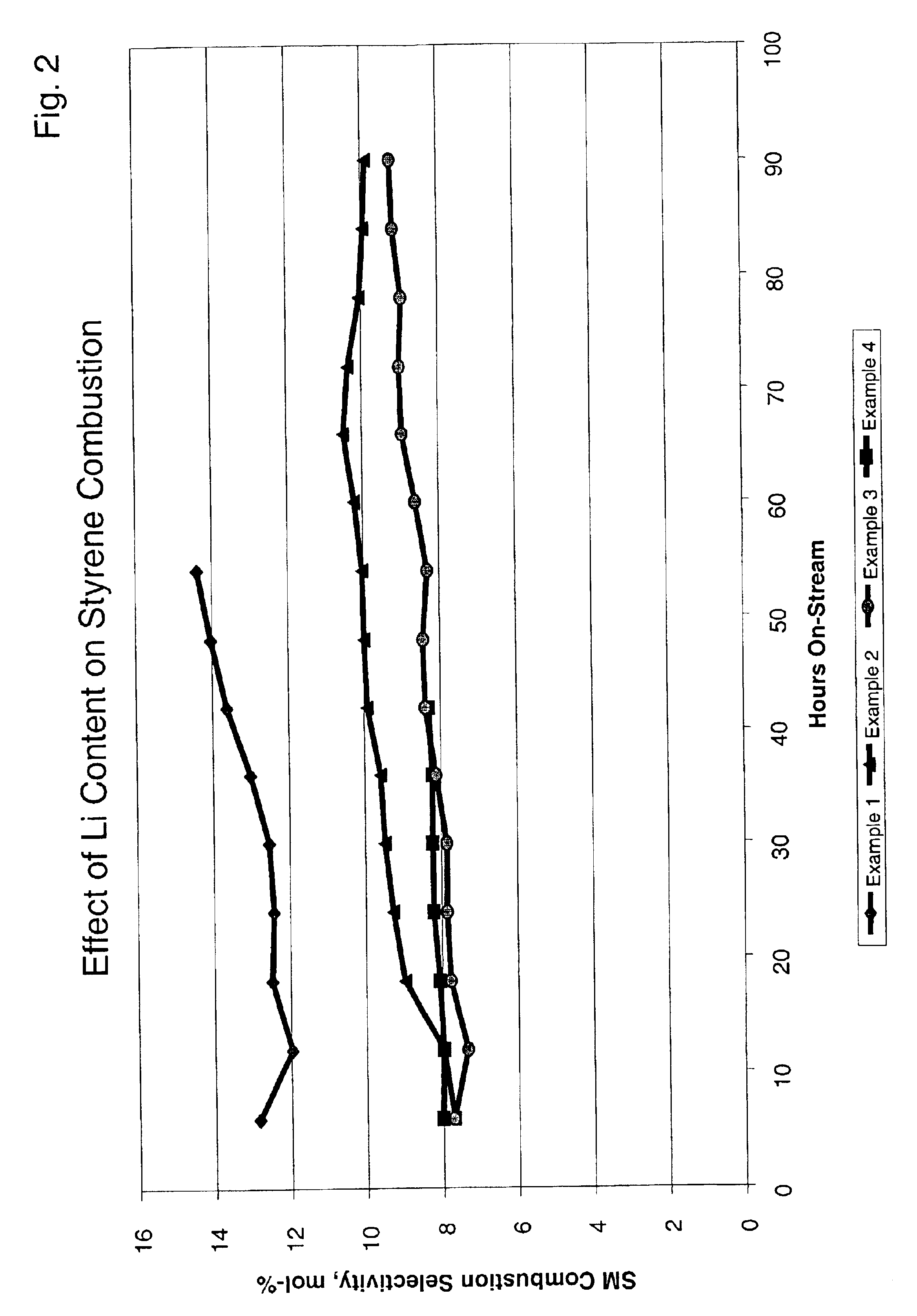
Lithium aluminate layered catalyst and a selective oxidation process using the catalyst
a technology of lithium aluminate and layered catalyst, which is applied in the direction of catalyst activation/preparation, metal/metal-oxide/metal-hydroxide catalyst, etc., can solve the problems of lowering the conversion level, affecting not only the conversion level but also the temperature drop
- Summary
- Abstract
- Description
- Claims
- Application Information
AI Technical Summary
Benefits of technology
Problems solved by technology
Method used
Image

Examples
example 1
A slurry was prepared by mixing 439.3 g of aluminum sol (15 wt. % Al2O3) and 118.8 g of 10% aqueous solution of polyvinyl-alcohol and 448.1 g of deionized water. To this mixture there were added 349.4 g of gamma-alumina power, which had been previously treated such that the particle size was less than 200 microns. After about 10 minutes of stirring using a mixer, 10.51 g of a 50% aqueous solution of stannic chloride (SnCl4) were added to the mixture, and the slurry was ball milled for about 4 hours at ambient temperature thereby reducing the maximum particle size to less than 40 microns. This slurry was sprayed onto cordierite cores having an average diameter of about 4.0 mm by using a granulating and coating apparatus for about 19 minutes to give an outer layer of about 100 microns.
This layered spherical support was dried at 150° C. for 2 hours and then calcined at 1000° C. for 12 hours in order to further convert the gamma alumina in the outer layer into theta alumina.
The calcined...
example 2
A slurry was prepared by mixing 439.3 g of an aluminum sol (15 wt. % Al2O3) and 118.8 g of a 10% aqueous solution of polyvinyl-alcohol and 448.1 g of deionized water. To this mixture there were added 349.4 g of gamma-alumina powder, which had been previously treated such that the particle size was less than 200 microns. After about 10 minutes of stirring using a mixer, 10.51 g of a 50% aqueous solution of stannic chloride (SnCl4) were added to the mixture and the slurry was ball milled for about 4 hours at ambient temperature thereby reducing the maximum particle size to less than 40 microns. This slurry was sprayed onto cordierite cores having an average diameter of about 4.0 mm by using a granulating and coating apparatus for about 19 minutes to give an outer layer of about 100 microns.
This layered spherical support was dried at 150° C. for 2 hours and then calcined at 1000° C. for 12 hours in order to further convert the gamma alumina in the outer layer into theta alumina.
The cal...
example 3
The procedure of Example 2 was repeated, except that the concentration of lithium nitrate solution added to the rotary impregnator was increased to result in a greater concentration of lithium on the catalyst. Elemental analysis showed that this catalyst contained 0.14 wt. % platinum, 0.16 wt. % tin and 0.72 wt. % lithium with respect to the entire catalyst. This catalyst was recovered and identified as catalyst C. X-ray diffraction analysis showed that the outer layer consisted of mixtures of lithium aluminate, i.e. LiAlO8 and LiAlO2.
PUM
| Property | Measurement | Unit |
|---|---|---|
| Temperature | aaaaa | aaaaa |
| Thickness | aaaaa | aaaaa |
| Pressure | aaaaa | aaaaa |
Abstract
Description
Claims
Application Information