Multi-jet impingement cooled slab laser pumphead and method

a laser pumphead and laser pumphead technology, applied in lasers, laser cooling arrangements, laser details, etc., can solve the problems of limited power, limiting thermal management of high-energy lasers in operation, and rod-shaped lasing media, and achieve the effect of convenient manufactur

Inactive Publication Date: 2005-02-22
RAYTHEON CO
View PDF9 Cites 33 Cited by
  • Summary
  • Abstract
  • Description
  • Claims
  • Application Information

AI Technical Summary

Benefits of technology

[0017]In another illustrative embodiment, the manifold has a plurality of exhaust vents formed therein such that plural portions of the plurality exhaust orifices couple the coolant fluid to each of the plurality of exhaust vents prior to the coolant fluid returning to the means for circulating. In a refinement to this embodiment, the flow axis of the plural of exhaust orifices and the plural exhaust vents are aligned along substantially different directions. In a particular embodiment, the different directions are orthogonal to one another. To effect a manifold design that is easier to manufacture, the plural exhaust orifices have a first end opening and a second end opening, and the first end opening is positioned to receive the coolant near the broad surface of the laser medium. The second end opening is sealed from the flow of coolant fluid and the plural orifices have a third opening that is coupled to one of the plural exhaust vents. The second end opening may be sealed with an ‘O’-ring.

Problems solved by technology

Solid state laser technology has advanced to the point where thermal management of high-energy lasers in operation is a limiting factor in scaling such systems to greater power levels.
Rod shaped lasing media have been used, but are power limited due to the limited surface area they present for coupling pumplight into the medium and for removal of waste heat energy.
Like all energy conversion processes, the efficiency of the lasing process can not achieve 100%.
Energy that is not converted into laser beam energy is waste energy that results in the production of sensible heat energy and fluorescence light energy.
Failure to remove the waste energy produces several deleterious effects that ultimately limit the maximum laser beam quality and the energy capability of the system.
Generally, an increase in operating temperature within the lasing medium reduces the efficiency of the lasing process.
Such induced birefringence is therefore undesirable, particularly in high-energy applications.
Such feedback is potentially damaging to the oscillator components.
Depolarization also reduces the output power and imprints a non-uniform intensity profile on the output beam, which adversely affects beam quality.
Multi-jet impingement cooling creates a variety of coolant flow issues that are not easily resolved when taken in combination with the need to control the thermal gradients in the slab.
Further, the prior art teachings do not address the issue of the removal of the fluorescence energy required in application with solid state diode-pumped laser.

Method used


Image

  • Multi-jet impingement cooled slab laser pumphead and method
  • Multi-jet impingement cooled slab laser pumphead and method
  • Multi-jet impingement cooled slab laser pumphead and method

Examples


Embodiment Construction

inlet openings according to an illustrative embodiment of the present invention.

[0025]FIG. 8 is a cross-section view of the inlet manifold, coolant manifold and laser slab according to an illustrative embodiment of the present invention.

[0026]FIG. 9 is a drawing of the impingement-jets and exhaust openings aligned with the laser slab according to an illustrative embodiment of the present invention.

[0027]FIG. 10 is a cross-section of a multi-jet impingement-cooled slab laser pumphead according to an illustrative embodiment of the present invention.

[0028]FIG. 11 is a section detail of a multi-jet impingement-cooled slab laser pumphead according to an illustrative embodiment of the present invention.

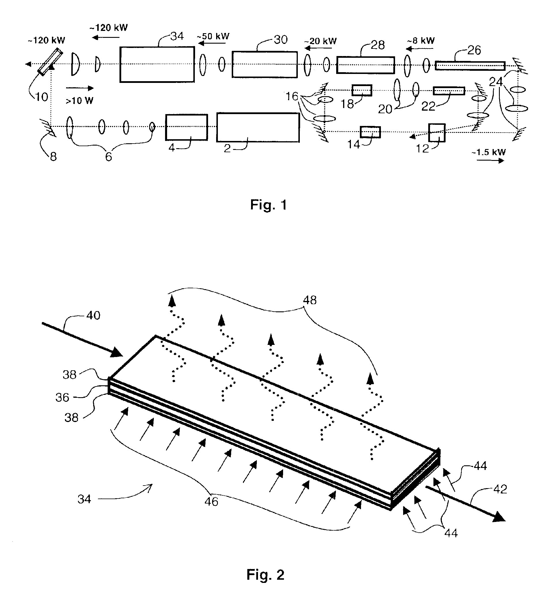
[0029]FIG. 12 is a thermal performance plot according to an illustrative embodiment of the present invention.

DESCRIPTION OF THE INVENTION

[0030]Illustrative embodiments and exemplary applications will now be described with reference to the accompanying drawings to disclose the advantageous t...


PUM


Abstract

A system for removing waste energy in the form of sensible heat and fluorescent energy from a solid state laser medium having a broad surface. The system includes a manifold disposed about the laser medium having a plurality of inlet jets interspersed with a plurality of exhaust orifices. Coolant fluid is circulated through the manifold. The fluid is forced through the plurality of inlet jets to impinge the broad face of the laser medium, thereby transferring waste energy by convection from the laser medium to the coolant fluid. The coolant fluid is further circulated to exhaust the pumphead manifold through the plurality of exhaust orifices. The fluorescent energy, which is radiated from the laser medium, is converted to sensible heat by an absorber disposed within the coolant adjacent to the laser medium. The coolant then removes the converted heat by forced convection. The absorber can be suspended particles in the coolant fluid or a porous material supported in the manifold at some distance from the laser medium.

Description

CROSS-REFERENCE TO RELATED APPLICATIONS[0002]This application claims priority from U.S. Provisional Application No. 60 / 350,630, filed Nov. 13, 2001 by Alexander A. Betin et al, entitled. MULTI-JET IMPINGEMENT COOLED SLABS LASER PUMPHEAD AND METHOD.BACKGROUND OF THE INVENTION[0003]1. Field of the Invention[0004]The present invention relates lasers. More specifically, the present invention relates to a system and method for cooling a high-power solid state laser.[0005]2. Description of the Related Art[0006]Solid state laser technology has advanced to the point where thermal management of high-energy lasers in operation is a limiting factor in scaling such systems to greater power levels. This is particularly true where high-energy laser system design parameters are constrained to limited size and weight. Thermal management technology advancement is therefore a key factor in increasing power output levels in high-energy solid state lasers.[0007]Current solid-state laser designs employ ...

Claims


Application Information

Patent Timeline
Patent Type & Authority Patents(United States)
IPC IPC(8): H01S3/04H01S3/042H01S3/06H01S3/23H01S3/02
CPCH01S3/042H01S3/025H01S3/0407H01S3/2333H01S3/0612H01S3/10076H01S3/2316H01S3/0606
Inventor BETIN, ALEXANDER A.GRIFFIN, WILLIAM S.
Owner RAYTHEON CO
Why Eureka
Try Eureka