Squelch detection circuit

a detection circuit and squelch technology, applied in the field of circuits, can solve the problems of inability to detect whether the transmitting data is a noise element, the peripheral equipment of personal computers or workstations is noticeably changing, and the conventional squelch detection circuit employing the foregoing comparator cannot. achieve the effect of convenient us

Inactive Publication Date: 2005-02-22
SAMSUNG ELECTRONICS CO LTD
View PDF3 Cites 26 Cited by
  • Summary
  • Abstract
  • Description
  • Claims
  • Application Information

AI Technical Summary

Benefits of technology

Further, the input level shifter having a source follower architecture serves to level up low differential input level to a voltage level that is compatible and easy to use, and includes P-channel metal oxide semiconductor (PMOS) transistors, and resistors. The input level shifter reacts even at a cross point of the differential input signals. The first reference voltage generator having a source follower architecture includes PMOS transistors whose gates are coupled to the ground voltage, and resistors. The amplifier for amplifying the differential voltage of the average voltage and the first reference voltage includes an inverted voltage amplifier. The second reference voltage generator utilizes the first reference voltage as an input voltage, and generates the second reference voltage by using variable resistors.
As is apparent from the foregoing, according to the squelch detection circuit of the invention, data elements (noise or signal) being transmitted in the data transmission system operating at high speed can be effectively detected, even at the cross point of two signals.

Problems solved by technology

In spite of making great strides in computers, in particular in personal computers from the middle of the 1990s, there have been limited changes in their peripheral equipment.
However, the peripheral equipment of personal computers or workstations is noticeably changing.
First, when differential receiver on a receiving end of the cable receives a differential data signal, the differential receiver utilizes a squelch detector to detect whether the signal of the connector is invalid.
Thirdly, in a case of a downstream transceiver, the differential envelope detector monitors whether the signal of the connector on the connector is in a high speed state.
As a result, the conventional squelch detection circuit employing the foregoing comparator cannot detect whether the transmitting data is a noise element or a signal element at the cross point of the two differential input signals.

Method used


Image

  • Squelch detection circuit
  • Squelch detection circuit
  • Squelch detection circuit

Examples


Embodiment Construction

The following detailed description is of the best modes presently contemplated by the inventors for practicing the invention. It should be understood that the description of these preferred embodiments is merely illustrative and that they should not be taken in a limiting sense.

A squelch detection circuit of the present invention detects data elements (noise or signal) being transmitted through a cable bus and provides the result for receiver to transmitter. The squelch detection circuit of the invention detects whether the transmitting data is a noise element or a signal element even at a cross point.

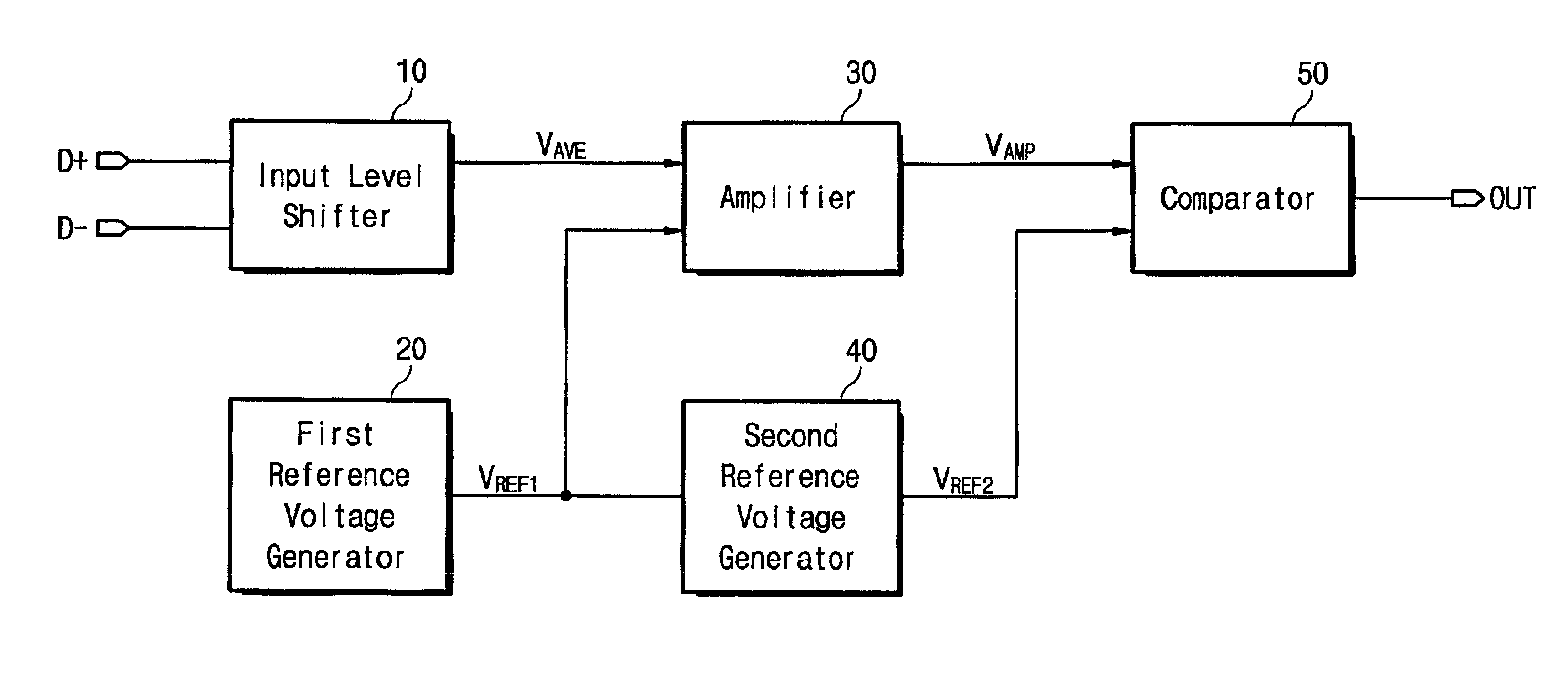
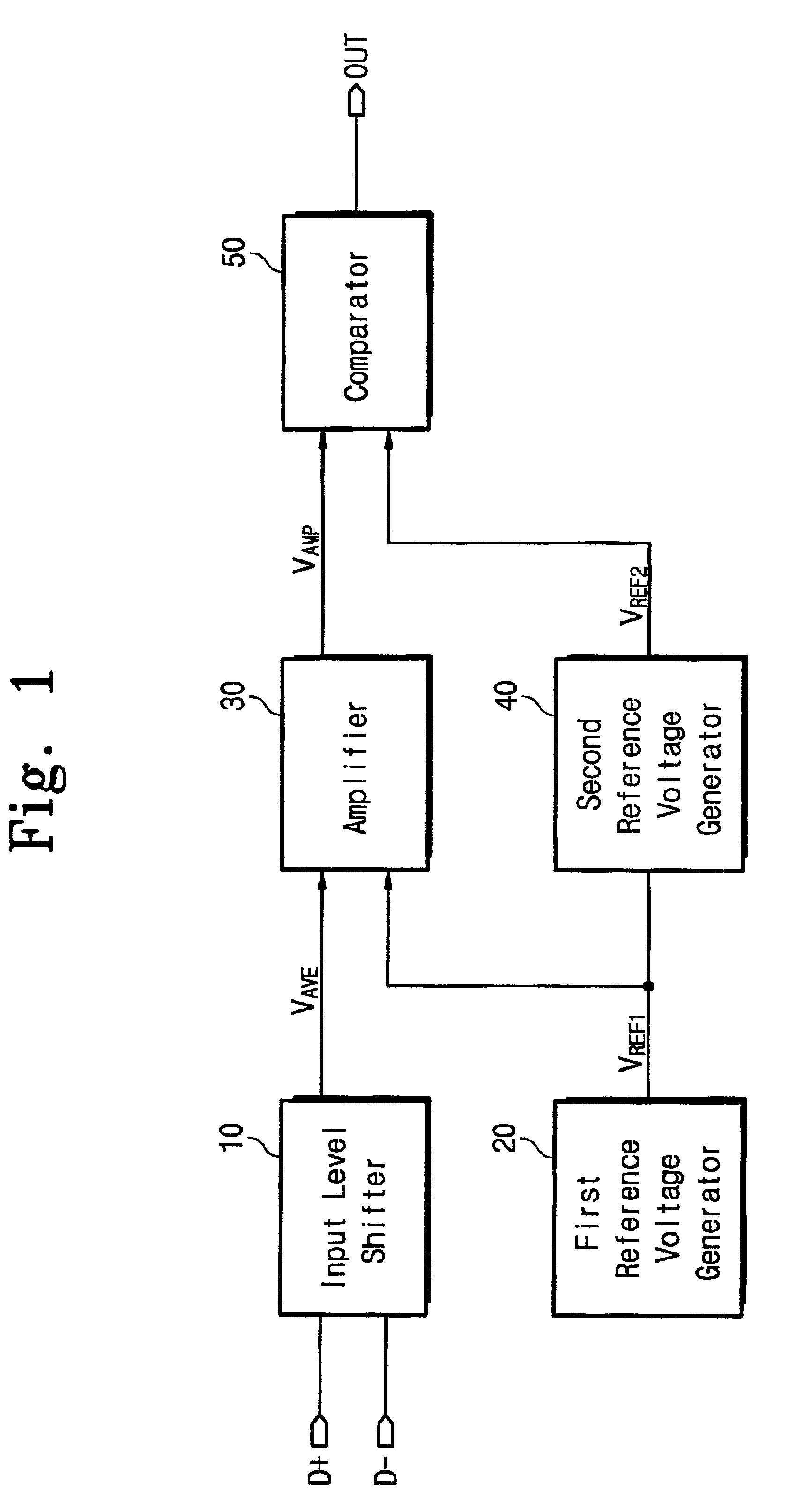
FIG. 1 is a block diagram of the squelch detection circuit according to an embodiment of the present invention. Referring to FIG. 1, the squelch detection circuit includes an input level shifter 10 generating an average voltage VAVE in response to a data signal through two signal lines D+ and D−. A first reference voltage generator 20 generates a first reference voltage VREF1 in respon...


PUM


Abstract

Disclosed is a transmission envelope detector referred to a squelch detection circuit for effectively detecting an element of transmission data in a high speed serial data transmission system. The squelch detection circuit of the invention includes a differential input level shifter, a first reference voltage generator, an amplifier, a second reference voltage generator, and a comparator. The squelch detection circuit can detect whether the transmission data is a noise or signal element even at a cross point of the transmission data, resulting in achieving stable data transmission.

Description

This application relies for priority upon Korean Patent Application No. 2001-16832, filed on Mar. 30, 2001, the contents of which are herein incorporated by reference in their entirety.FIELD OF THE INVENTIONThe present invention generally relates to a circuit for providing an interface between a bus and one or more devices connected thereto in digital data processing systems, and more particularly to a squelch detection circuit detecting data components in interfacing general-purpose serial buses such as wire cables connecting computers to peripheral equipment with devices connected to the buses.BACKGROUND OF THE INVENTIONIn spite of making great strides in computers, in particular in personal computers from the middle of the 1990s, there have been limited changes in their peripheral equipment. However, the peripheral equipment of personal computers or workstations is noticeably changing. Some such changes are due to new general-purpose buses, for example, USB (universal serial bus)...

Claims


Application Information

Patent Timeline
Patent Type & Authority Patents(United States)
IPC IPC(8): G06F13/40G06F13/38
CPCG06F13/4072G06F13/38
Inventor YU, JAE-SUK
Owner SAMSUNG ELECTRONICS CO LTD
Why Eureka
Try Eureka