Multiple magnet system with different magnet properties

a multi-magnet system and magnet technology, applied in the field of dynamic magnet systems, can solve problems such as interference with motion, and achieve the effects of increasing the sensitivity of applied motion, reducing the interference, and increasing the coupling

Inactive Publication Date: 2005-03-01
TELEDYNE SCI & IMAGING
View PDF43 Cites 26 Cited by
  • Summary
  • Abstract
  • Description
  • Claims
  • Application Information

AI Technical Summary

Benefits of technology

The present invention provides a dynamic multiple magnet system which achieves a greater coupling between a support structure for the magnets and the motion imparted to the magnets themselves. This enables a greater electrical output for a given device size and weight, and also allows the magnets to be oriented for movement in a primarily horizontal direction, thus greatly increasing their sensitivity to applied motion.

Problems solved by technology

However, the vertical orientation interferes with the motion of the magnets, which have to fight gravitational forces in order to move relative to the tube.

Method used


Image

  • Multiple magnet system with different magnet properties
  • Multiple magnet system with different magnet properties
  • Multiple magnet system with different magnet properties

Examples


Embodiment Construction

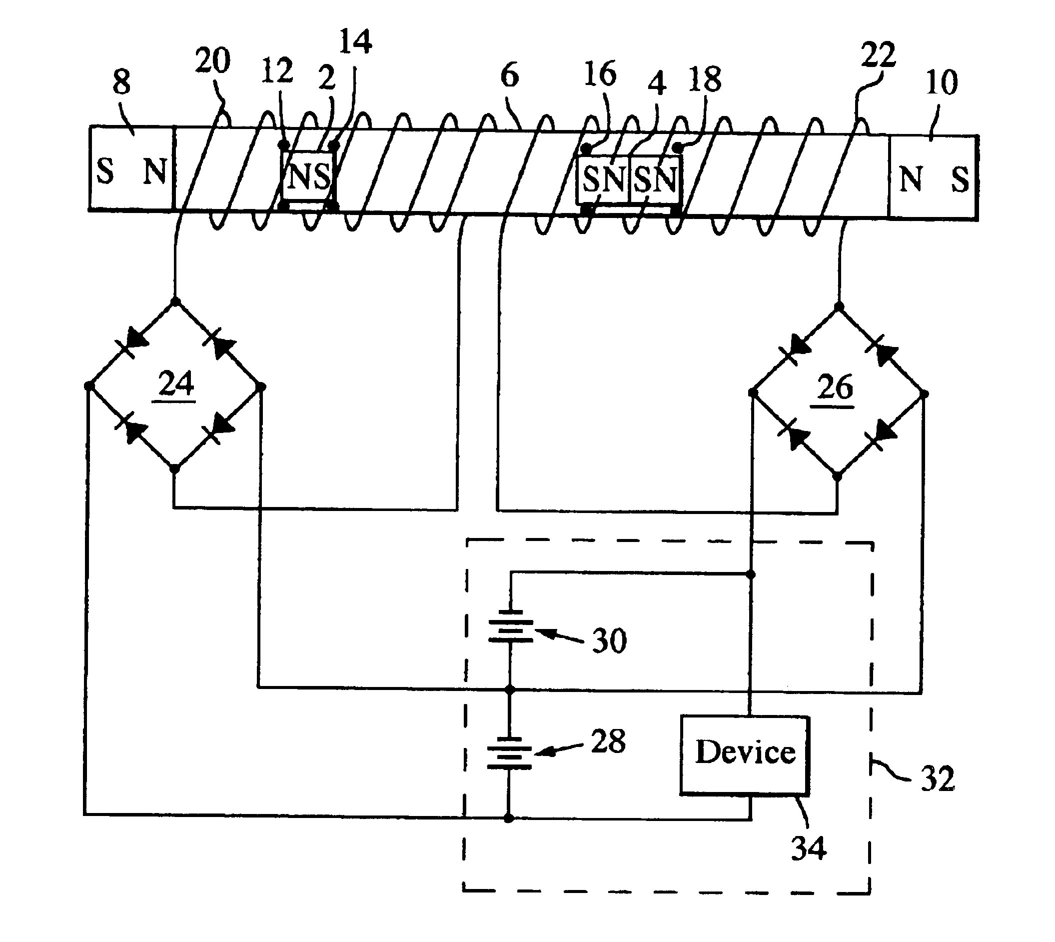
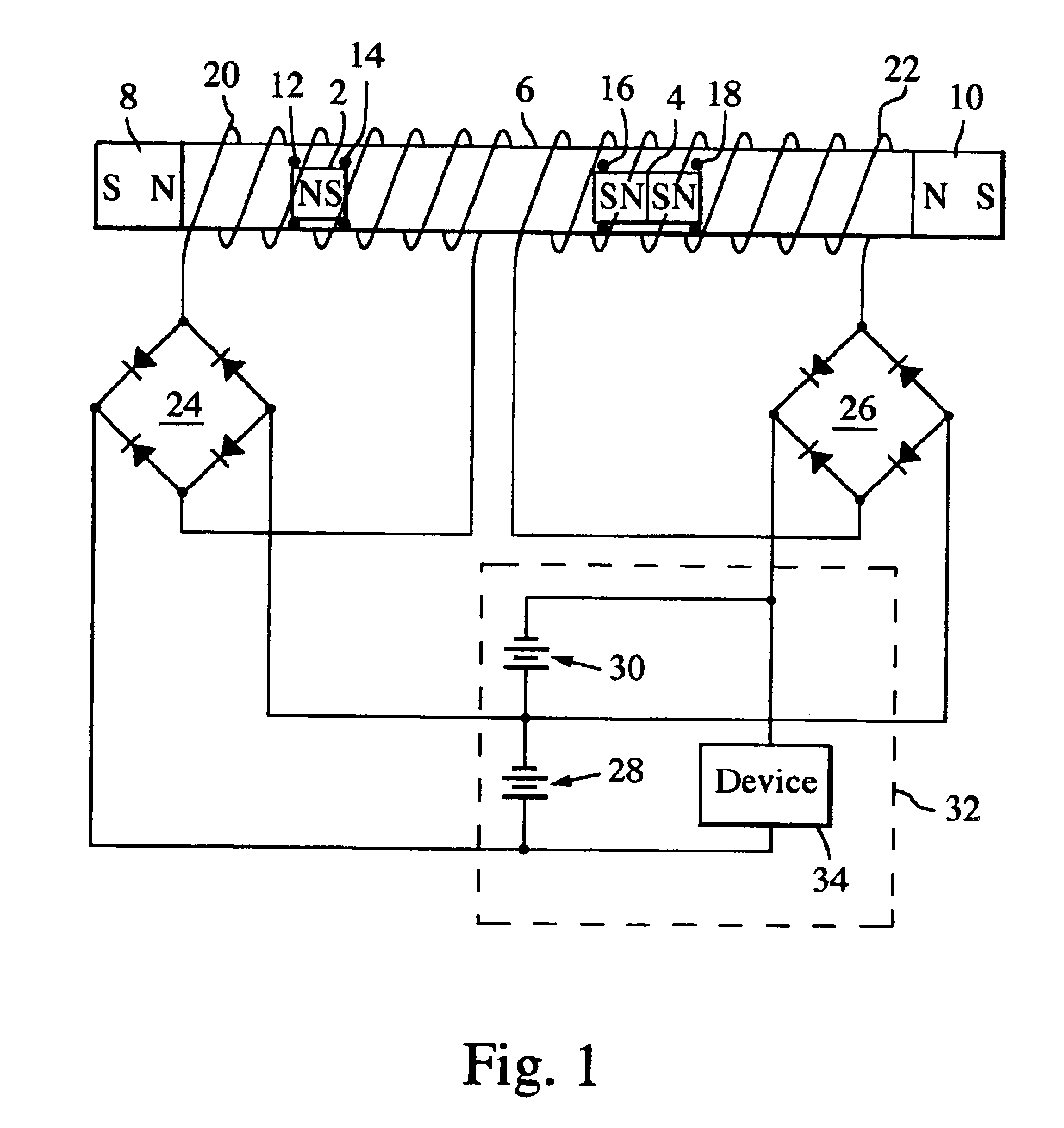
The present invention provides for more effective and flexible electrical power generation than has previously been available in reciprocating or oscillating magnet systems. Electricity can be effectively generated from very slight movements of the magnet support structure off a horizontal plane and / or movements in a horizontal plane. For example, a walking motion or other normal motions such as turning, tapping, bowing, or even riding in a vehicle that is subject to vibration, can easily generate useful amounts of electricity when the support structure for the magnets is held in the user's hand or in a shirt pocket, while slight off-horizontal movements due to wave or wind action can also be used for electrical generation.

The invention employs multiple magnets that move relative to a common support structure. It is not restricted to the three magnets required for the multi-magnet system of U.S. Pat. No. 5,181,132, but rather can employ virtually any number of magnets, including eve...


PUM


Abstract

A dynamic magnet system, particularly useful for electrical generation, employs multiple magnets in polar opposition to each other for individual movement relative to a support structure. The magnets have a critical angle of displacement from a horizontal static position of less than 1 degree, with at least some of the magnets having mutually different properties. With different magnetic strengths, a greater movement is produced for both magnets in response to movements of the support structure, for particular ranges of magnetic strength ratios, than would be the case with equal magnets. The magnet movement can be translated into an electrical signal to power an operating system. Ultra low friction ferrofluid bearings can be used to establish static coefficients of friction between the magnets and support structure less than 0.02, enabling useful power generation from only slight movements of the support structure.

Description

BACKGROUND OF THE INVENTION1. Field of the InventionThis invention relates to dynamic magnet systems, and more particularly to multiple-magnet systems used to generate electric power.2. Description of the Related ArtMoving a magnet through a conductive coil induces a current flow in the coil. If the magnet is moved back and forth in a reciprocating motion, the direction of current flow in the coil will be reversed for each successive traverse, yielding an AC current.Several electrical generating systems have been disclosed that make use of reciprocating magnet movement through one or more coils. For example, in various embodiments of U.S. Pat. No. 5,347,185, one, two or three rare earth magnets are positioned to move linearly back and forth relative to one or more coils. The magnets can either be fixed and the coil moved up and down relative to the magnet, as by wave action, the coil can be fixed and the magnet moved relative to the coil as by pneumatic pressure, or the coil housing...

Claims


Application Information

Patent Timeline
Patent Type & Authority Patents(United States)
IPC IPC(8): H02K35/02H02K35/00H02K7/08H02K1/00
CPCH02K35/02
Inventor CHEUNG, JEFFREY T.XIN, HAO
Owner TELEDYNE SCI & IMAGING
Why Eureka
Try Eureka