Charger system with dual-level current regulation and dual-level thermal regulation

a charging system and current regulation technology, applied in electric vehicles, electric power, transportation and packaging, etc., can solve the problems of single package unit limited power dissipation capability, serious problem, and main system shutdown, and achieve the effect of increasing the overall efficiency of the adapter-charger system

Inactive Publication Date: 2005-03-01
ANALOG DEVICES INC
View PDF7 Cites 77 Cited by
  • Summary
  • Abstract
  • Description
  • Claims
  • Application Information

AI Technical Summary

Benefits of technology

One advantage of the present invention is that the invention provides a comprehensive charger control system and method for a device that may reside in a single package. The comprehensive control system assures an optimal charging current at all times without violating overall adapter current limits or exceeding maximum allowable operating temperatures.
Another advantage of the present invention is that the present invention enables more power management functions to be integrated into a single device and increases the overall efficiency of the adapter-charger system.
Yet another advantage is that the invention provides a simple yet comprehensive charger contro

Problems solved by technology

This contention can cause a serious problem.
If the battery is not sufficiently charged, power to the main system 13 would be abruptly lost, thereby shutting the main system 13 down.
It is well-known that a single package unit has a limited power dissipation capability.
However, there is no control circuit to guarantee that the battery voltage does not cause a voltage drop greater than 0.8 Volts across the linear charger 42 but the temperature control circuit provides a limit on power dissipation if the voltage drop across the linear charger is too great.
Ho

Method used


Image

  • Charger system with dual-level current regulation and dual-level thermal regulation
  • Charger system with dual-level current regulation and dual-level thermal regulation
  • Charger system with dual-level current regulation and dual-level thermal regulation

Examples


Embodiment Construction

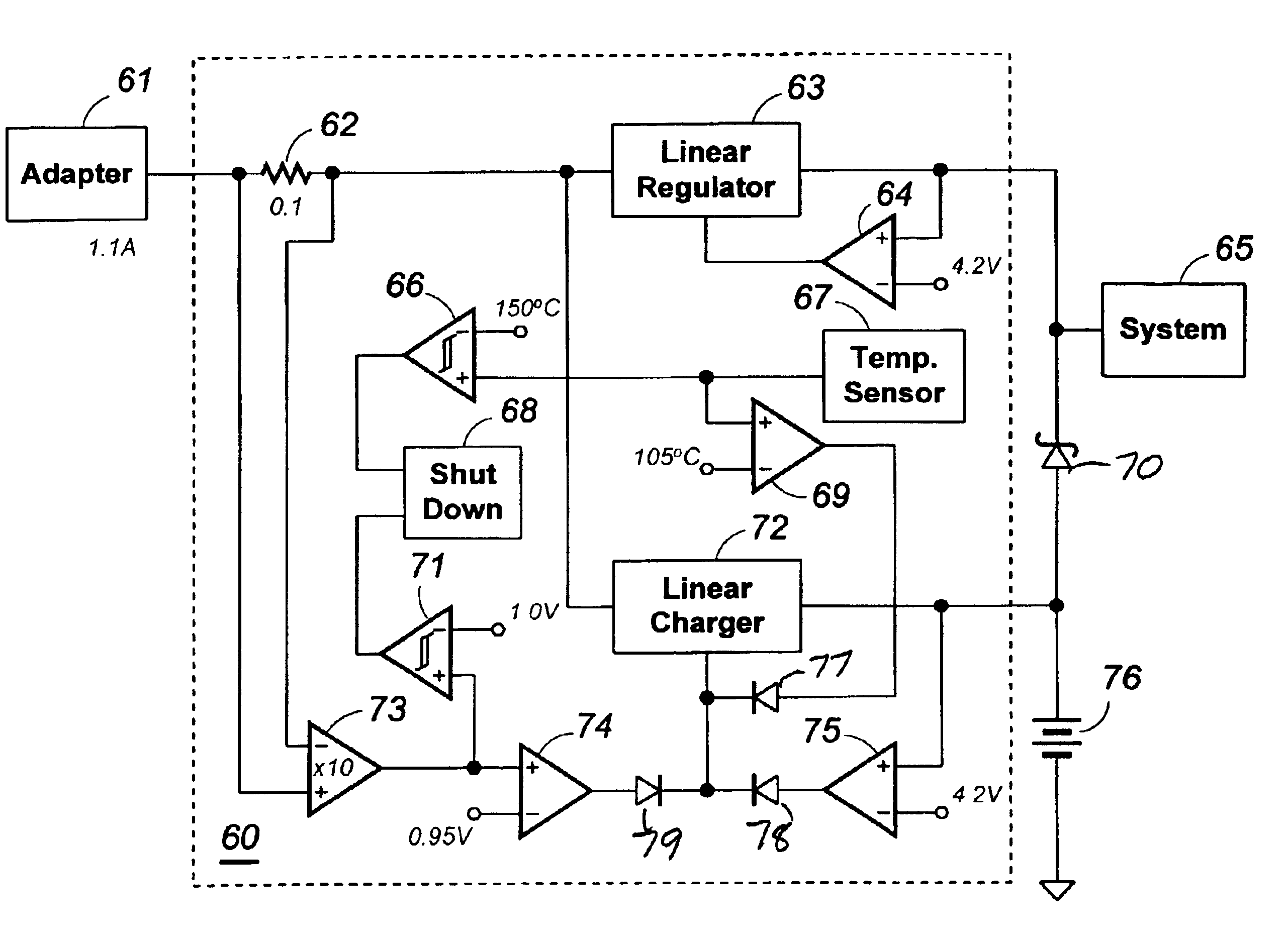
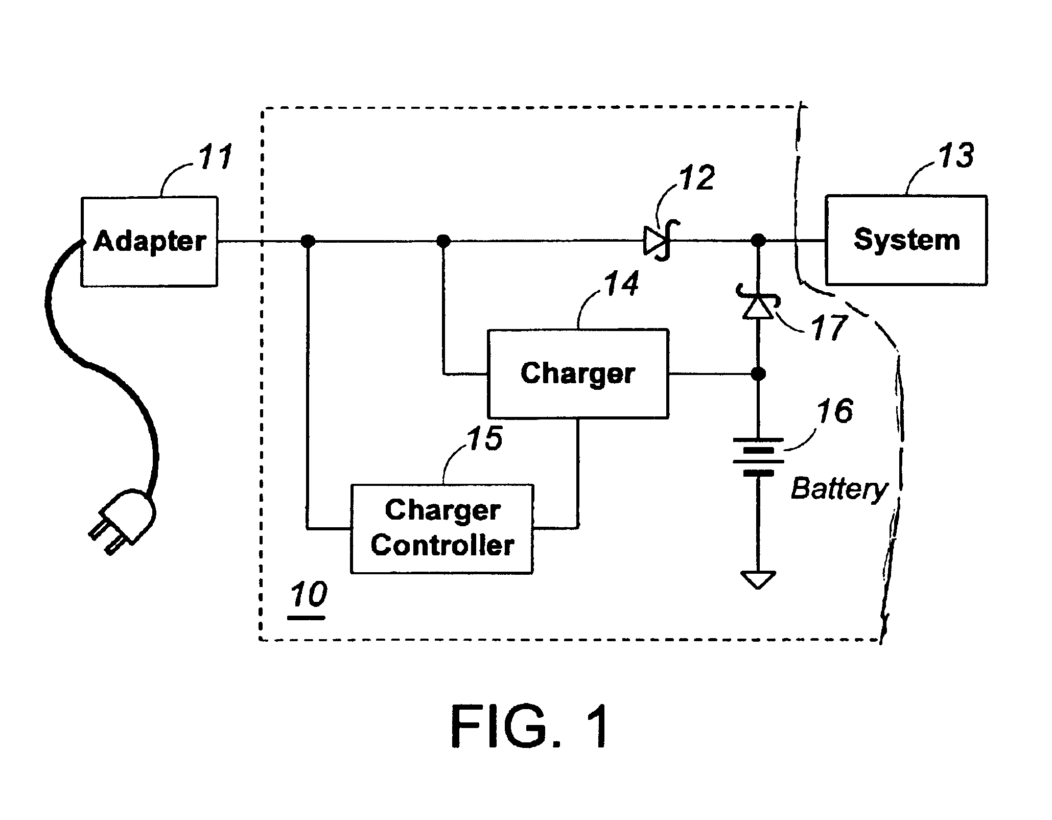
In many portable electronic devices, further integration of power management functions into an adapter-charger system is required. For example, Schottky diodes 12 and 17, shown in FIG. 1, may need to be replaced by power MOSFETs to achieve higher efficiency and reduced heat dissipation. A power MOSFET may be used for either or both of the Schottky diodes 12, 17.

FIG. 5 shows a charging circuit with a power MOSFET that replaces a pass diode of the prior art. In FIG. 5, power MOSFET 52 replaces the pass-through Schottky diode 12 of FIG. 1. Power MOSFET 52 supplies the current required for running the system when adapter 51 is connected to a power source and to the charging system 50. Because power MOSFET 52 resides on the same substrate as linear charger 54, both contribute heat dissipation to charger system 50. In other words, the temperature rise of charger system 50 derives from two sources. Furthermore, control circuit 55 now must provide thermal limit protection to prevent linear ...


PUM


Abstract

A charging system that concurrently charges a main system and a battery for powering the main system when the charging system is connected to an adapter. The charging system includes a current sensing resistor, a first current control circuit for regulating the current in a linear battery charger and a second current control circuit for controlling the maximum adapter current. The charging system further includes a first temperature control circuit for regulating the current in the battery charger and a second temperature control circuit for controlling the maximum power dissipation of the charging system. The charging system further includes a linear regulator for providing power to the main system from the adapter and a main system voltage control circuit and a battery voltage control circuit. The charging system apportions the adapter current between the main system and the battery charger giving priority to the main system.

Description

CROSS-REFERENCE TO RELATED APPLICATIONS1. Field of the InventionThe present invention generally relates to battery chargers and more particularly to battery chargers that support system operation while charging.2. Description of the Related ArtFIG. 1 shows a typical battery charger system that supports charging while operating a main system 13. The system can be a portable electronic device such as a cellular phone handset and the charger can be a unit built-in to the portable device. The charging system 10 includes a rechargeable battery 16, a charger 14, a charger controller 15, and a pair of Schottky diodes 12, 17. An external adapter 11 is connected to the positive side of Schottky diode 12 to provide power to the battery 16 via the charger 14 and to the main system 13. When charging system 10 is not connected to the adapter 11, the main system 13 is powered by battery 16 via Schottky diode 17. Schottky diode 12 prevents battery 16 from activating charger 14, which would otherwi...

Claims


Application Information

Patent Timeline
IPC IPC(8): H02J7/00
CPCH02J7/0068
Inventor LIU, KWANG H.NEGRU, SORIN L.SHIH, FU-YUAN
Owner ANALOG DEVICES INC
Why Eureka
Try Eureka