Methods for making composite bonded structures

a composite material and bonding technology, applied in the field of composite materials and the infiltration method for producing the same, can solve the problem of weak bonding condition of the subunits

Inactive Publication Date: 2005-03-08
BUSINESS ALLIANCE CAPITAL
View PDF16 Cites 15 Cited by
  • Summary
  • Abstract
  • Description
  • Claims
  • Application Information

AI Technical Summary

Benefits of technology

These objects and other desirable attributes of the present invention are accomplished through the use of techni

Problems solved by technology

Often during thermal processing, adhesive binders may be pyrolyzed or even

Method used


Image

  • Methods for making composite bonded structures
  • Methods for making composite bonded structures
  • Methods for making composite bonded structures

Examples


example 1

This example demonstrates the fabrication of a silicon carbide composite “U channel” featuring a multi-constituent infiltrant phase.

Preforms were prepared by a sedimentation casting process. Specifically, about 25 parts of liquid were added to 100 parts of CRYSTOLON blocky (regular), green silicon carbide (St. Gobain / Norton Industrial Ceramics, Worchester, Mass.) and 8 to 12 parts of KRYSTAR 300 crystalline fructose (A.E Staley Manufacturing Co., Decatur, IL) to make a slurry. The silicon carbide particulate consisted of about 70 parts by weight of Grade F 240 (median particle size of about 44 microns) and the balance Grade F 500 (median particle size of about 13 microns). The solids and liquids were added to a plastic jar and roll mixed for about 40 hours. The slurry was de-aired in about 760 mm of vacuum for about 5 minutes. About 15 minutes prior to casting, the slurry was re-roll mixed to suspend any settled particulates.

A graphite support plate was placed onto a vibration table...

example 2

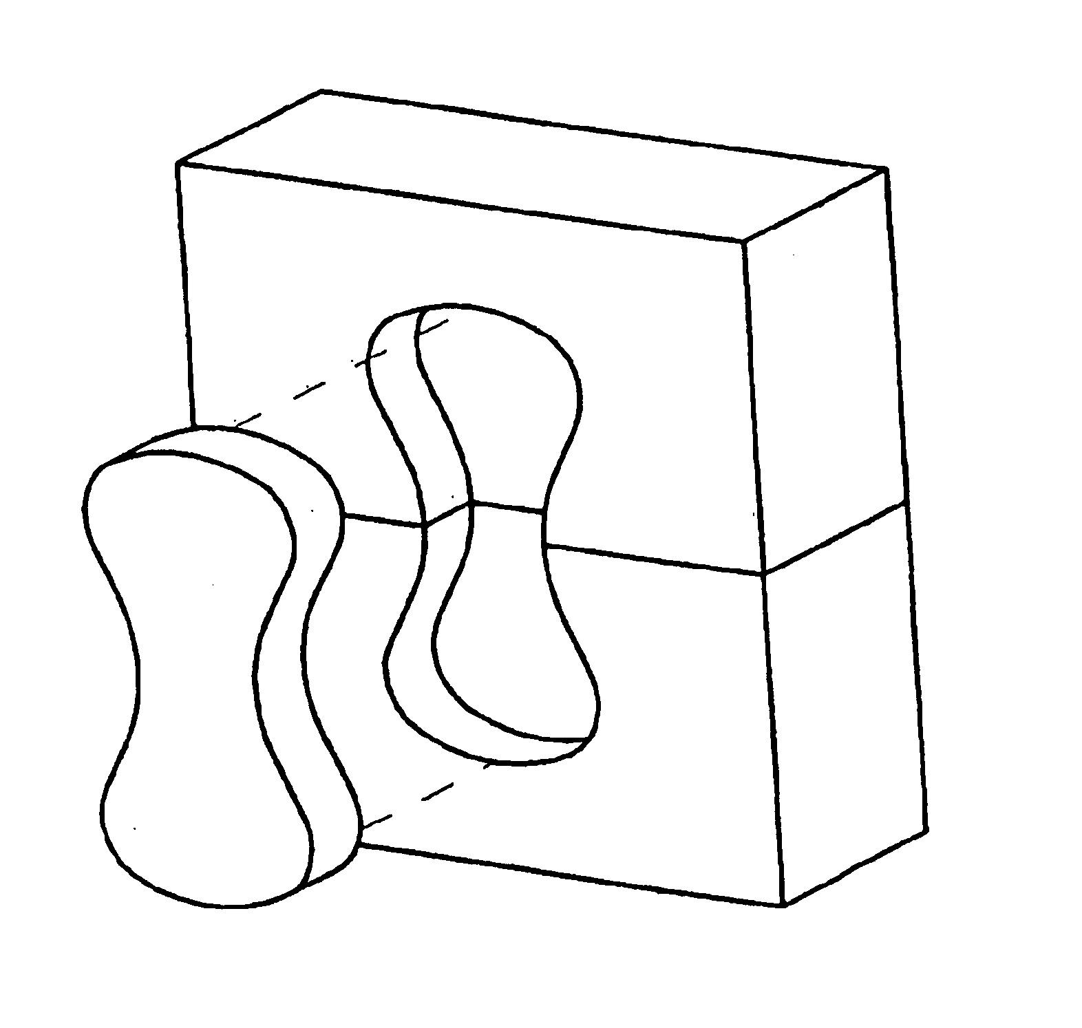
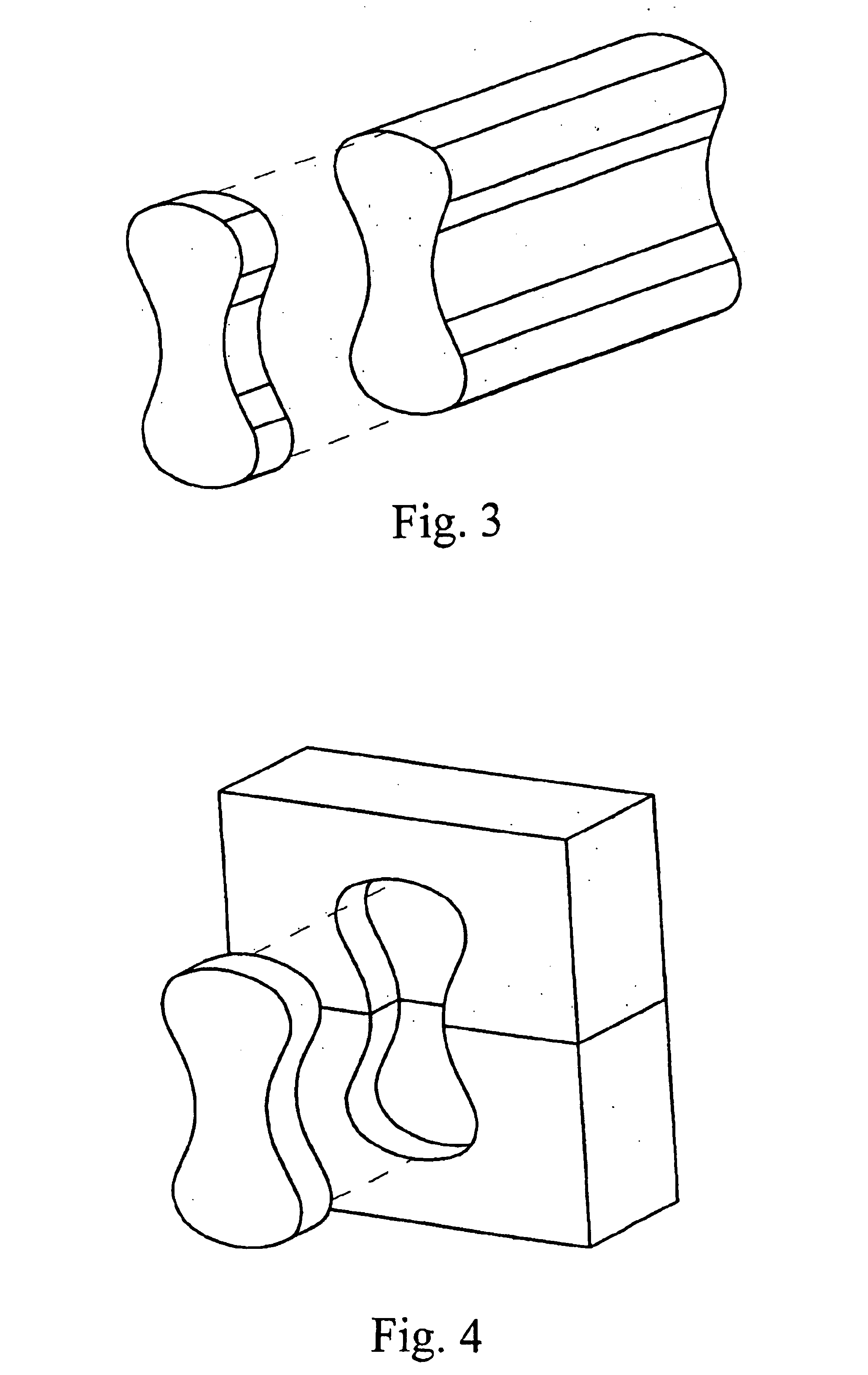
This example demonstrates the fabrication of a silicon carbide composite air bearing support frame featuring a multi-constituent infiltrant phase. This example also demonstrates the fabrication of a relatively complex composite body by way of making a bonded assemblage of smaller preform subunits, and then infiltrating the assemblage.

An air bearing support frame preform was fabricated in two longitudinal sections using substantially the same sediment casting slurry as was described in Example 1. Following sedimentation casting and freezing, the preform halves were dried to a temperature of about 150 C, with a carefully controlled heating up to this temperature to avoid cracking the parts due to the potential for excessive water vapor generation. The preform halves were then additionally thermally processed in a nitrogen atmosphere substantially in accordance with the heating described in Example 1 to pyrolyze the fructose binder to carbon. The preforms could then be green machined.

A...

example 3

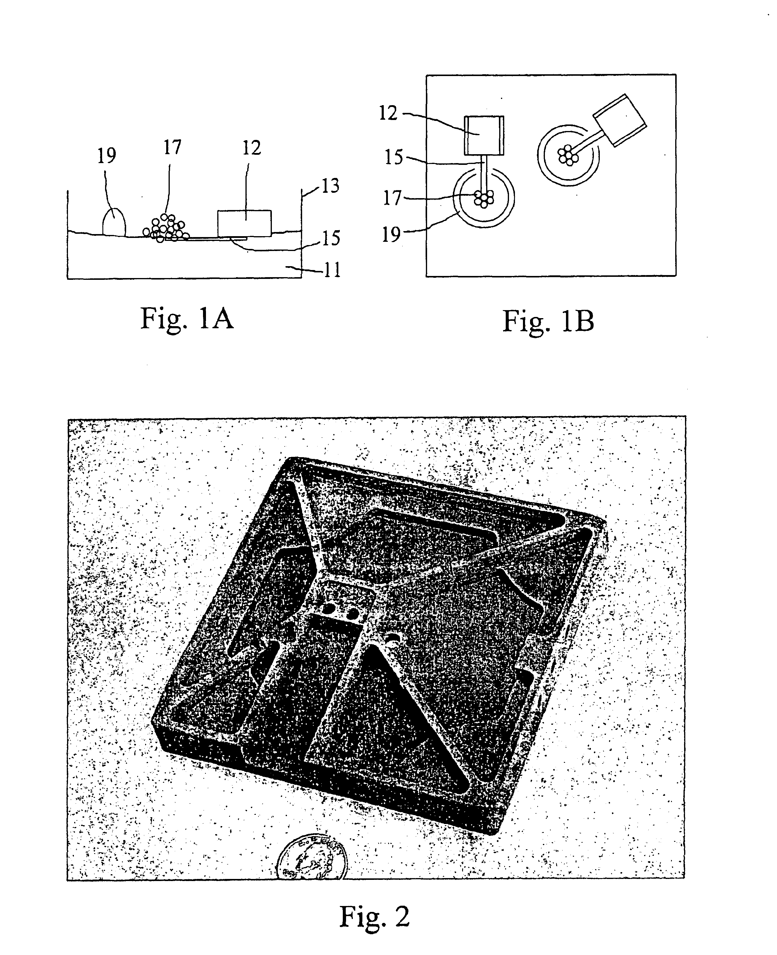
An air bearing support frame measuring about 120 mm square and about 19 mm in height was fabricated substantially along the lines described in Example 2 except that bonding of the two pieces was not carried out until after each piece had been infiltrated with silicon-aluminum alloy to form a reaction bonded silicon carbide composite part.

FIG. 2 shows the more complex-shaped piece of the two in the as-infiltrated condition.


PUM

PropertyMeasurementUnit
Fractionaaaaaaaaaa
Fractionaaaaaaaaaa
Electric chargeaaaaaaaaaa

Abstract

Techniques to bond two or more smaller bodies or subunits to produce a unitary SiC composite structure extend the capabilities of reaction-bonded silicon carbide, for example, by making possible the fabrication of complex shapes. In a first aspect of the present invention, two or more preforms are bonded together with a binder material that imparts at least strength sufficient for handling during subsequent thermal processing. In a second aspect of the present invention, instead of providing the subunits to be bonded in the form of preforms, the subunits may be dense, SiC composite bodies, e.g., RBSC bodies. In each of the above embodiments, a preferable means for bonding two or more subunits combines aspects of adhesive and mechanical locking characteristics. One way to accomplish this objective is to incorporate a mechanical locking feature to the joining means, e.g., a “keyway” feature. The mechanical locking feature thus substitutes for, or supplements the binder qualities of the adhesive, which is especially important when the adhesive itself may be or become weak due to, for example, thermal processing.

Description

BACKGROUND OF THE INVENTION1. Field of the InventionThe present invention relates to improved composite materials and the infiltration methods for producing the same. Specifically, the present invention relates to complex-shaped composite bodies produced from a bonded assemblage of smaller, simpler shapes. Even more specifically, the present invention relates to silicon carbide composites wherein preferably at least a portion of the silicon carbide is produced by reactive infiltration.2. Discussion of Related ArtSilicon carbide composites have been produced by reactive infiltration techniques for more than thirty-five years. In general, such a reactive infiltration process comprises contacting molten silicon with a porous mass containing silicon carbide plus carbon in a vacuum or an inert atmosphere environment. A wetting condition is created, with the result that the molten silicon is pulled by capillary action into the mass, where it reacts with the carbon to form additional silic...

Claims


Application Information

Patent Timeline
IPC IPC(8): C04B35/573C04B35/565C04B37/00C04B35/65
CPCC04B35/573C04B35/62665C04B35/65C04B37/008C04B35/63452C04B37/005C04B35/62655C04B2237/09C04B2235/3206C04B2235/3217C04B2235/3804C04B2235/3813C04B2235/3821C04B2235/3826C04B2235/3843C04B2235/3847C04B2235/3865C04B2235/3873C04B2235/3886C04B2235/40C04B2235/401C04B2235/402C04B2235/404C04B2235/405C04B2235/407C04B2235/408C04B2235/421C04B2235/428C04B2235/48C04B2235/5427C04B2235/5436C04B2235/5472C04B2235/6562C04B2235/6565C04B2235/725C04B2235/94C04B2235/6567C04B2235/658C04B2237/365C04B2237/525C04B2237/61C04B2237/66C04B2237/083
Inventor RICHMOND, MICHAEL A.AGHAJANIAN, MICHAEL K.MCCORMICK, ALLYN L.WAGGONER, W. MICHAELSCHULTZ, BRIAN E.
Owner BUSINESS ALLIANCE CAPITAL
Why Eureka
Try Eureka