
Gate structure and method of forming the gate dielectric with mini-spacer

a gate dielectric and spacer technology, applied in the direction of semiconductor devices, electrical apparatus, transistors, etc., can solve the problems of poor dimensional control of the fet channel length, difficult to remove etch residues, and difficult to achieve high-quality oxides without defects, so as to improve the control of the gate length and improve the effect of the gate length

Inactive Publication Date: 2005-03-15
TAIWAN SEMICON MFG CO LTD
View PDF11 Cites 33 Cited by
  • Summary
  • Abstract
  • Description
  • Claims
  • Application Information

AI Technical Summary

Benefits of technology

Accordingly, it is a primary object of the invention to describe a simple method to form a gate structure with high-k dielectric gate and mini-spacer surrounding the gate.
A further object of the invention is to provide an FET device with a gate structure having a high-k gate dielectric with improved control of gate length and an integral mini-spacer.
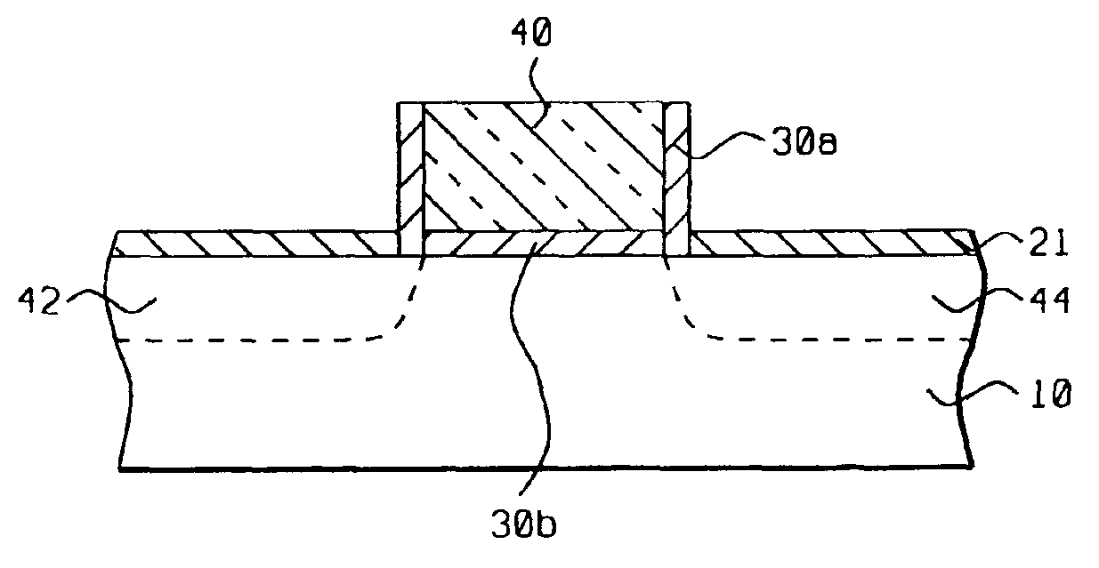
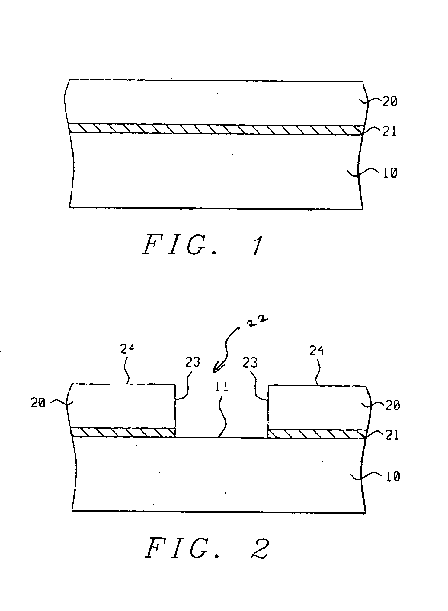
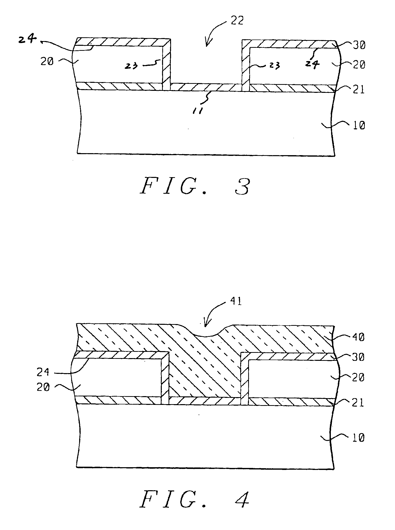
In accordance with these objectives, a method is described to fabricate a gate structure with high-k dielectric material, a mini-spacer of the same high-k material, and improved gate length. The high-k gate film is patterned damage-free and without leaving any process residues. A trench pattern is formed in a disposable dummy film that is deposited over a silicon substrate. A high-k dielectric film liner is then deposited within said trench pattern. The trench, with high-k film as the liner, is then filled with poly-silicon gate conductor. The structure is then planarized preferably using chemical mechanical polishing method or other etch-back processes, such that said high-k film on the planar surfaces of the dummy film is also removed during the planarizing step, thereby leaving the high-k film liner only inside the trenches. The dummy film around the gate is then removed to leave a structure with mini-spacer of high-k material surrounding the gate. Because the process uses a deposition method to form the high-k gate structure within a dummy trench, the gate length is much more precisely defined as compared to methods using etching process to pattern high-k gate.

Problems solved by technology

If silicon dioxide has to be used in ULSI devices with short channel length, it needs to be quite thin to achieve large capacitance values and formation of nanometer range, high quality oxides without defects is quite difficult if not impossible.
However, patterning of high-k films, unlike the conventional silicon oxides or nitrided oxides, is difficult for two main reasons: i) plasma etching of these films that do not easily form volatile reaction products requires high self-developed or applied bias voltages will cause device damage of the silicon surface of the transistor and ii) alternatively, non damaging wet etching processes result in poor dimensional control of the FET channel length and are prone to etch residues that are hard to remove during post-processing steps.
Although the high-k materials like cobalt niobate, barium strontium nitrate (BST), and tantalum oxide are proposed, the process described is quite complex and it is very likely that etch residues will be left on the silicon substrate when etching the high-k film within the gate trenches and around the gate structure, as previously discussed.

Method used


Image

  • Gate structure and method of forming the gate dielectric with mini-spacer
  • Gate structure and method of forming the gate dielectric with mini-spacer
  • Gate structure and method of forming the gate dielectric with mini-spacer

Examples


Embodiment Construction

The process described in the present invention provides a simplified method to fabricate a gate structure in an FET semiconductor device with a high-k gate dielectric and a mini-spacer, without producing any device damage or leaving any process residues. Although in the present invention a dummy trench is etched in nitride or organic BARC film, any material that can be easily patterned using conventional wet or plasma etching process can be used.

Referring now to FIG. 1, there is shown a substrate 10 that is silicon of desired crystallographic orientation in this embodiment having other parts of the FET device already formed (not shown) in it. A disposable dummy film 20, is then deposited over substrate 10 using standard deposition methods such as: chemical vapor deposition (CVD), plasma enhanced CVD (PE-CVD), or spin coating known in prior art. The dummy film can be of inorganic type selected from a group of inorganic materials comprising silicon nitride, silicon oxy-nitride, silico...


PUM


Abstract

A field effect transistor gate structure and a method of fabricating the gate structure with a high-k gate dielectric material and high-k spacer are described. A gate pattern or trench is first etched in a dummy organic or inorganic film deposited over a silicon substrate with source / drain regions. A high-k dielectric material liner is then deposited on all exposed surfaces. Excess poly-silicon gate conductor film is then deposited within and over the trench to provide adequate overburden. Poly-silicon is then planarized with chemical mechanical polishing or etch-back methods such that the high-k material film on top of the dummy film surface is removed during this step. In the final step, the dummy film is disposed off, leaving the final transistor gate structure with high-k gate dielectric and high-k spacer surrounding the gate conductor poly-silicon, with the entire gate structure fabricated to form an FET device on a silicon substrate.

Description

BACKGROUND OF THE INVENTION(1) Field of the InventionThe present invention relates generally to methods of fabricating a gate dielectric and a mini-spacer, and more particularly, to methods of patterning gate structures with high-k gate dielectric films and mini-spacers in the fabrication of semiconductor devices and integrated circuits.(2) Description of the Prior ArtThe current generation ultra large-scale integrated (ULSI) circuits use predominantly field effect transistor (FET) devices, having poly-silicon gate electrode, silicon dioxide gate dielectric, and self-aligned source / drain regions. Typical process of fabricating an FET consists of growing a thin gate silicon dioxide on a silicon substrate and then forming the poly-silicon gate electrode. Source / drain (S / D) regions are then formed adjacent to the gate electrode, which then defines the FET gate length as the distance under the poly-silicon gate between the S / D regions. The gate length and the control of gate length is c...

Claims


Application Information

Patent Timeline
Patent Type & Authority Patents(United States)
IPC IPC(8): H01L21/70H01L29/66H01L21/8238H01L29/80H01L21/265H01L29/78
CPCH01L21/2652H01L29/78H01L29/518H01L29/517
Inventor CHIU, YUAN-HUNGTSAI, MING-HUANCHEN, FANG-CHENGTAO, HUN-JAN
Owner TAIWAN SEMICON MFG CO LTD
Learn More