Wiring line assembly and method for manufacturing the same, and thin film transistor array substrate having the wiring line assembly and method for manufacturing the same

Inactive Publication Date: 2005-03-15
SAMSUNG DISPLAY CO LTD
View PDF11 Cites 31 Cited by
  • Summary
  • Abstract
  • Description
  • Claims
  • Application Information

AI Technical Summary

Benefits of technology

It is an object of the present invention to provide a thin film transistor array substrate

Problems solved by technology

However the wiring lines of silver or silver alloy cannot easily adhere to the underlying substrate o

Method used


Image

  • Wiring line assembly and method for manufacturing the same, and thin film transistor array substrate having the wiring line assembly and method for manufacturing the same
  • Wiring line assembly and method for manufacturing the same, and thin film transistor array substrate having the wiring line assembly and method for manufacturing the same
  • Wiring line assembly and method for manufacturing the same, and thin film transistor array substrate having the wiring line assembly and method for manufacturing the same

Examples


Embodiment Construction

Preferred embodiments of this invention will be explained with reference to the accompanying drawings.

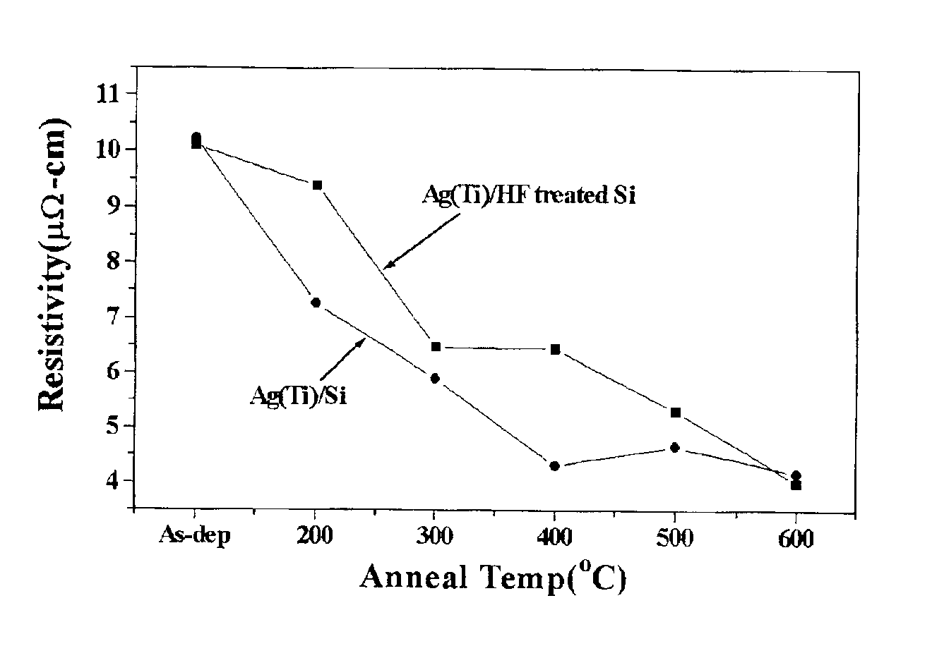
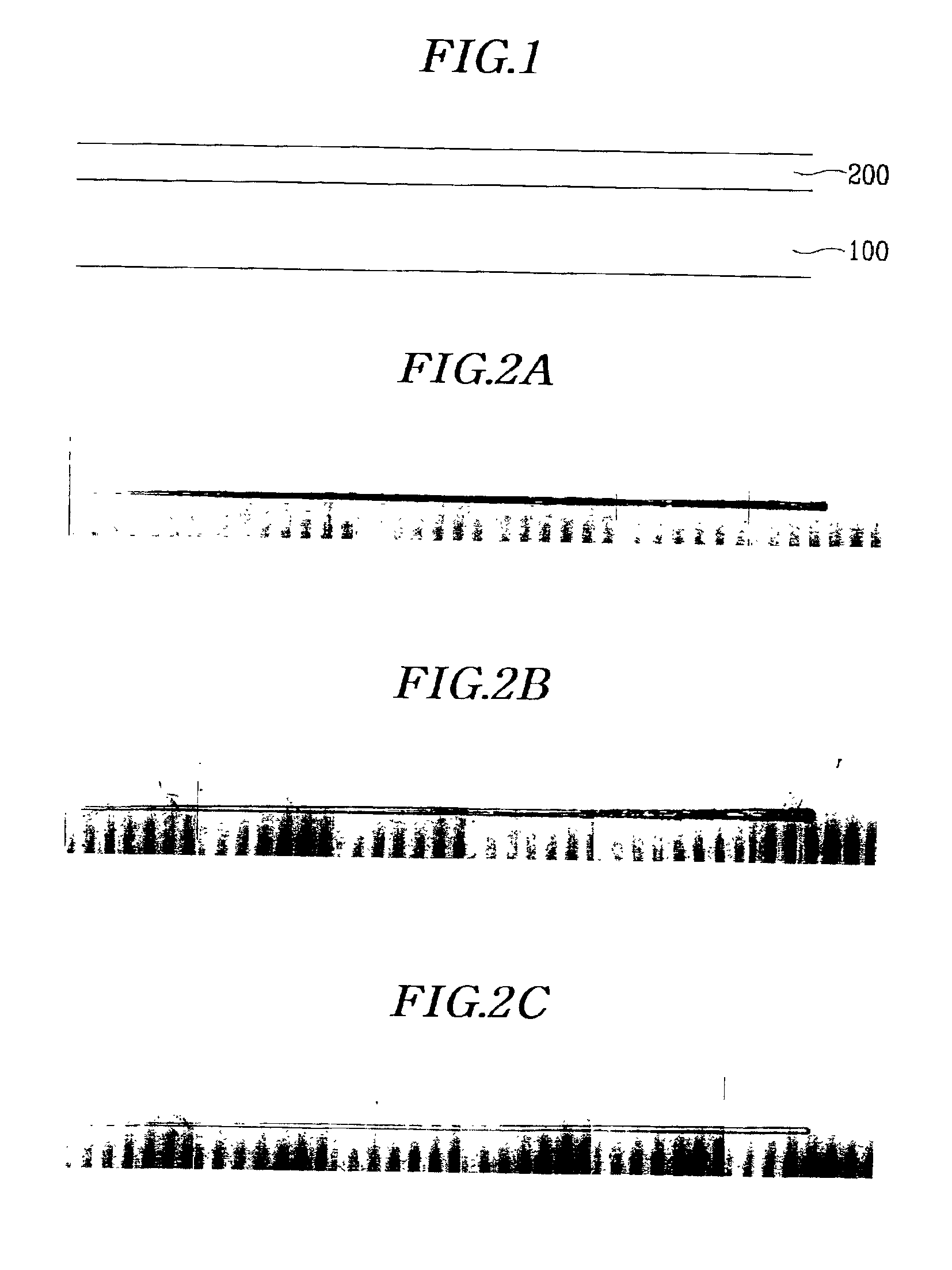
FIG. 1 is a cross sectional view of a thin film deposited onto a glass or silicon substrate.

In order to fabricate a wiring line assembly for a semiconductor device or a display device, as shown in FIG. 1, a thin film 200 based on a conductive material having a low resistance such as silver and silver alloy is deposited onto a substrate 100, and patterned through photolithography. In the case of a silver alloy-based thin film 200, it may be formed with a main content of silver (Ag), and an alloy content of conductive material of 0.01-20 atomic % or less. The alloy content may have one or two conductive material components selected from Pd, Cu, Mg, Al, Li, Pu, Np, Ce, Eu, Pr, Ca, La, Nb, Nd, or Sm. That is, a double or triple-sourced silver alloy may be used for the thin film 200.

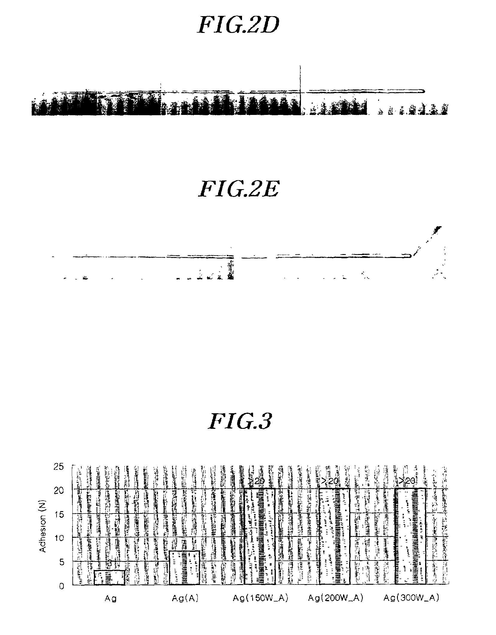
As the silver or silver alloy-based thin film 200 adheres poorly to the underlying substrate 100, it is re...


PUM


Abstract

In a method for fabricating a thin film transistor array substrate, a glass substrate undergoes an oxygen plasma treatment. A silver or silver alloy-based conductive layer is deposited onto the substrate, and patterned to thereby form a gate line assembly proceeding in the horizontal direction. The gate line assembly includes gate lines, gate electrodes, and gate pads. Thereafter, a silicon nitride-based gate insulating layer is deposited onto the substrate, and a semiconductor layer and an ohmic contact layer are sequentially formed on the gate insulating layer. The semiconductor layer and the ohmic contact layer are HF-treated. A silver alloy-based conductive layer is deposited onto the substrate, and patterned to thereby form a data line assembly. The data line assembly includes data lines crossing over the gate lines, source electrodes, drain electrodes, and data pads. A protective layer based on silicon nitride or an organic material is deposited onto the substrate, and patterned through dry etching such that the protective layer bears contact holes exposing the drain electrodes, the gate pads and the data pads, respectively. An indium zinc oxide or indium tin oxide-based layer is deposited onto the substrate, and patterned to thereby form pixel electrodes, and subsidiary gate and data pads. The pixel electrodes are electrically connected to the drain electrodes, and the subsidiary gate and data pads to the gate and data pads.

Description

BACKGROUND OF THE INVENTION(a) Field of the InventionThe present invention relates to a wiring line assembly and method of manufacturing the same, and thin film transistor array substrate having the wiring line 10 assembly and method of manufacturing the same.(b) Description of the Related ArtGenerally, wiring lines for a semiconductor device or a display device are used for signal transmission, and hence, it becomes important for such wiring lines to minimize signal delay.For that purpose, it is required that the wiring lines should be formed with a conductive material having a low resistance. For instance, silver (Ag) may be used for such a conductive material. However the wiring lines of silver or silver alloy cannot easily adhere to the underlying substrate or thin film. Therefore, the wiring lines are liable to become detached from the substrate or thin film.SUMMARY OF THE INVENTIONIt is an object of the present invention to provide a thin film transistor array substrate which ...

Claims


Application Information

Patent Timeline
IPC IPC(8): G02F1/13G02F1/1362H01L21/70H01L27/12H01L29/40H01L21/84H01L29/49H01L23/52H01L23/532G02F1/1345G02F1/1368G09F9/00G09F9/30H01L21/3205H01L21/336H01L21/77H01L29/43H01L29/786
CPCG02F1/13458G02F1/136286H01L27/124H01L29/4908H01L27/1288H01L27/12G02F2001/13629G02F2001/136295H01L23/53242H01L2924/0002H01L2924/00G02F1/13629G02F1/136295H01L29/786
Inventor JEONG, CHANG-OHKANG, BONG-JOOLEE, JAE-GAB
Owner SAMSUNG DISPLAY CO LTD
Why Eureka
Try Eureka