Cutting tool and method of using same

a cutting tool and cutting method technology, applied in the field of improved cutting tools, can solve the problems of tungsten carbide wear quickly when worn, requiring much larger forces to fracture the rock, and formation of wear fla

Inactive Publication Date: 2005-03-22
COMMONWEALTH SCI & IND RES ORG
View PDF65 Cites 19 Cited by
  • Summary
  • Abstract
  • Description
  • Claims
  • Application Information

AI Technical Summary

Benefits of technology

According to the present invention, there is provided a cutting tool for cutting hard rock, said cutting tool including one or more cutting elements each comprising a pointed or chisel shaped body including a diamond composite material including diamond

Problems solved by technology

Principally, tungsten carbide wears quickly when used to cut abrasive rock.
In practice, most tips do not rotate, resulting in the formation of wear flat.
Even tips which do rotate as intended wear to a cone which contacts the rock surface along a line rather than at a point, thereby requiring much larger forces to fracture the rock compared to when the tip was new.
Because of this wear, tungsten carbide tips can only effectively be used for cutting coal or soft rock.
Accordingly, the average life span of a tungsten carbide tip is short and it must be replaced frequently.
Due to the wear characteristics of the tungsten carbide tips, rock wheels are limited to use on rocks having a strength limit of about 100 to 120 MPa, such as sandstones.
Accordingly, while they can be quite successfully used on soft rocks, rock wheels cannot be used on harder rock, such as granite.
While such saws can be used to cut hard rock, the sawing process is very energy intensive and very slow.
However, due to the rapid wear of the tungsten carbide, these drill bits are not practical for use in drilling hard rock, such as granite.
However, such attempts have been unsuccessful due to distortion of tungsten carbide or decom

Method used


Image

  • Cutting tool and method of using same
  • Cutting tool and method of using same
  • Cutting tool and method of using same

Examples


first embodiment

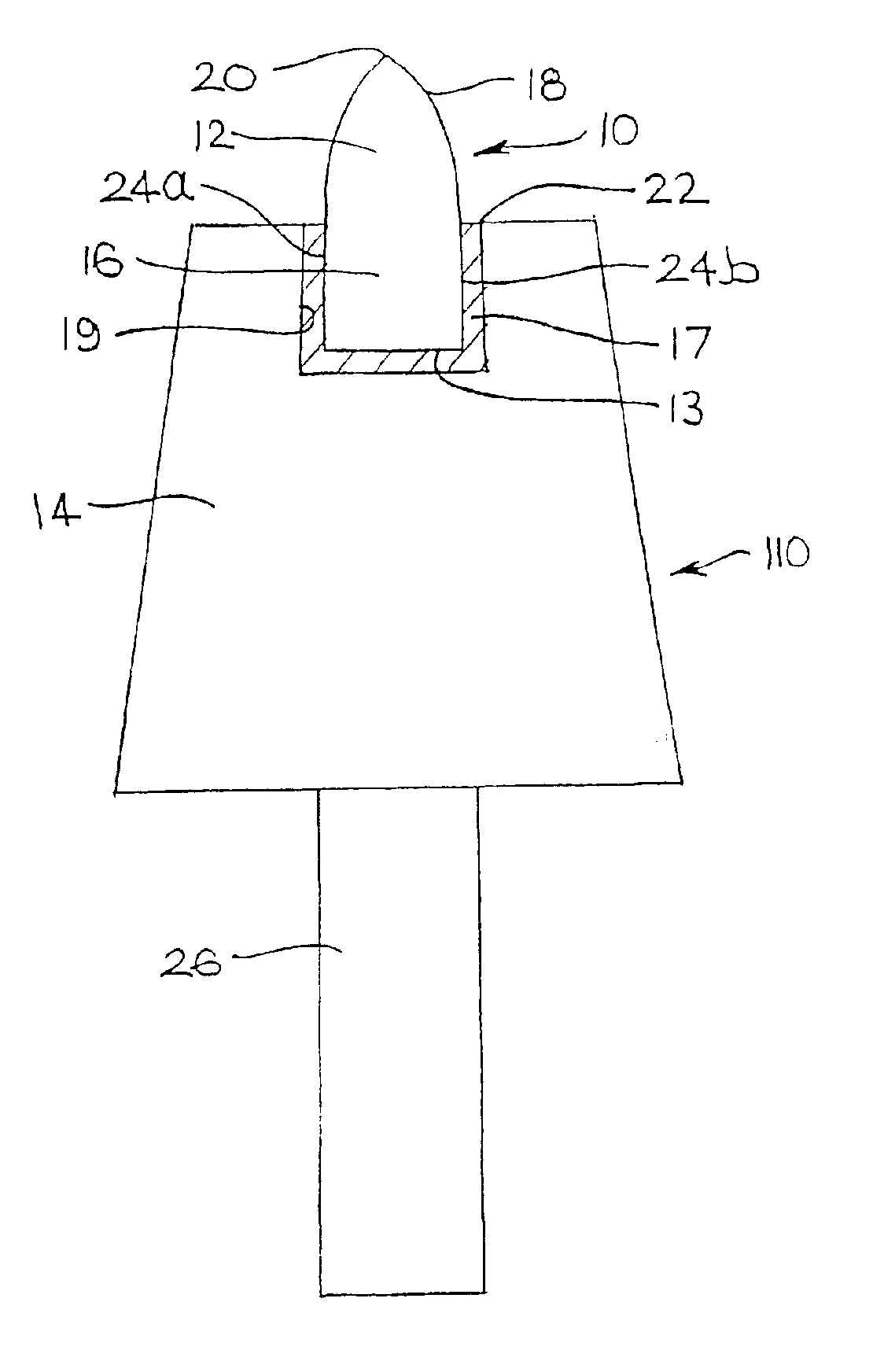
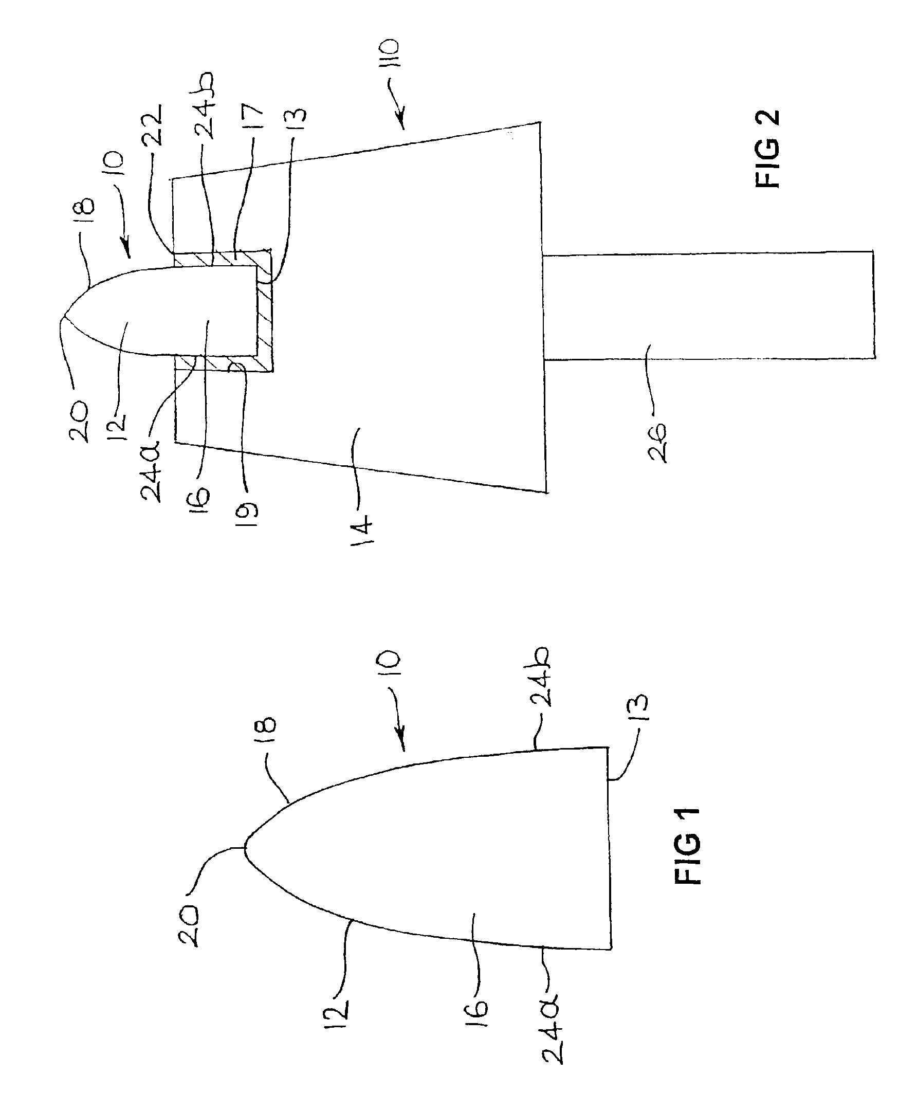
FIG. 2 is a schematic cross-sectional view of a pick according to the present invention.

second embodiment

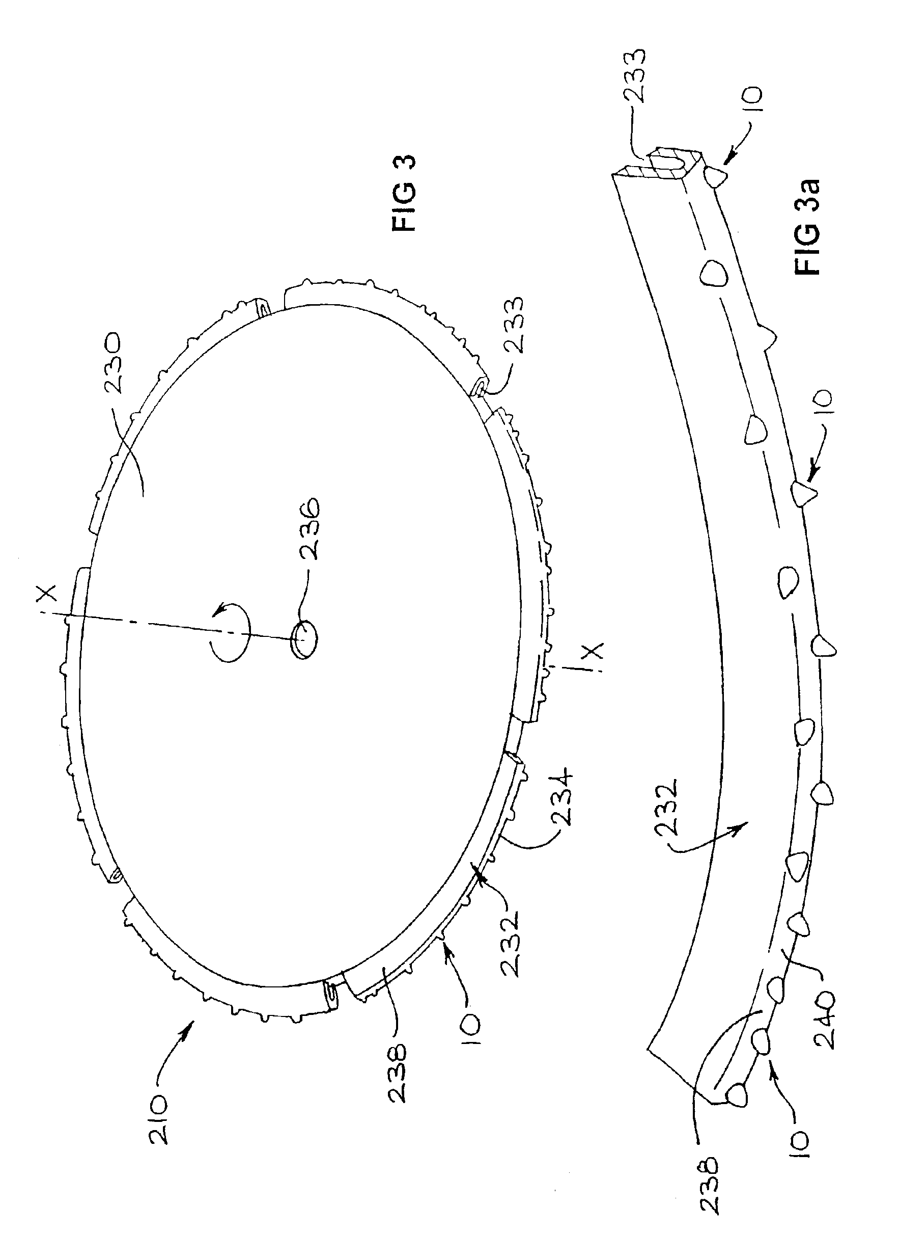
FIG. 3 is a perspective view of a saw according to the present invention.

FIG. 3a is a detailed perspective view of a cutting segment of the saw illustrated in FIG. 3.

FIG. 4 is a perspective view of a modified version of the saw illustrated in FIG. 3.

FIG. 4a is a detailed cut-away view of the periphery of the saw illustrated in FIG. 4.

third embodiment

FIG. 5 is a perspective view of a coring drill bit according to the present invention.

DETAILED DESCRIPTION OF THE PREFERRED EMBODIMENTS

In the following detailed description of the preferred embodiments as illustrated in the accompanying drawings, like reference numerals refer to like parts.

FIG. 1 shows a cross section of a cutting element 10 comprising a pointed body 12 formed from ADC. The cutting element 10 comprises a base 13, an elongate mounting portion 16, which is adapted to be received in the supporting matrix of a tool body (not shown) and a cutting portion 18 on which is provided the cutting surface or point 20. The cutting point 18 is ogival, or bullet shaped whereas the sides 24a, 24b of the mounting portion 16 taper inwardly from the base 13 to the cutting portion 18.

In FIG. 2, a pick 110 is illustrated which includes a cutting element 10 comprising a pointed body 12 formed from ADC mounted in a pick body 14 made from steel. The cutting element 12 includes the features ...


PUM

PropertyMeasurementUnit
Angleaaaaaaaaaa
Angleaaaaaaaaaa
Angleaaaaaaaaaa

Abstract

A cutting tool for cutting hard rock, the cutting tool including one or more cutting elements each including a pointed or chisel-shaped body including a diamond composite material including diamond crystals bonded together by a silicon carbide matrix, the each cutting element being mounted into a supporting matrix including a metal matrix composite material, such that the point or chisel edge of the each element protrudes from the matrix.

Description

FIELD OF THE INVENTIONThis invention relates to improved cutting tools for the cutting, drilling or sawing of hard materials, such as rock, stone, concrete and the like. The invention particularly relates to a pick, a saw and a drill, each including a diamond composite tip, and methods of using same.BACKGROUND OF THE INVENTIONMachinery employed in the excavation, mining, cutting, working, or drilling of rock, stone, concrete and similar hard materials employ a variety of tools, hereinafter collectively referred to as “cutting tools”. Three commonly used types of cutting tools are picks, saws and drills.PicksPicks are used as cutting tools in machinery used in such applications as the mining of coal and the tunnelling through of rock. The term “pick” (also called “drag-tool”) typically means a pointed or chisel shaped rock cutting tool which cuts rock by penetrating and scraping along the surface of the rock. Picks typically consist of a steel shank with a tungsten carbide-cobalt mat...

Claims


Application Information

Patent Timeline
IPC IPC(8): E21C35/183E21C35/00E21B10/46E21B10/56E21C35/18E02F9/28E21B10/567E21D9/087
CPCE21B10/567E21C35/183E21C2035/1826E21C2035/1816E21C2035/1806E21C35/1831E21C35/188E21C35/1837
Inventor BOLAND, JAMES NORMANBUNKER, KITWILLIS, PAUL EDWIN
Owner COMMONWEALTH SCI & IND RES ORG
Why Eureka
Try Eureka