Heat recovery in an olefin production process

a technology of heat recovery and olefins, which is applied in the direction of catalytic naphtha reforming, organic chemistry, hydrocarbon preparation catalysts, etc., can solve the problems of catalysts being subjected to great mechanical stresses, nitrogen and sulfur impurities that require expensive purification steps, and olefins from an oto process involve unique technical challenges

Inactive Publication Date: 2005-03-22
EXXONMOBIL CHEM PAT INC
View PDF13 Cites 45 Cited by
  • Summary
  • Abstract
  • Description
  • Claims
  • Application Information

AI Technical Summary

Benefits of technology

The present invention is a process for controlling accumulation of catalyst solids in the recovery train of the oxygenate to olefin process. The process comprises providing an effluent stream from an oxygenate to olefin reaction. The effluent stream comprises solid particles and a gas phase. The gas phase contains prime olefins and has a dew point. The process also comprises removing heat from the effluent stream while maintaining a temperature of the gas phase above the dew point during the step of removing heat. Additionally, the process also includes washing the effluent stream in a solids wash to remove solid particles from effluent stream into a wash medium.

Problems solved by technology

However, the cracking process produces nitrogen and sulfur impurities that require expensive purification steps.
Nonetheless, effluent from the OTO process comprises olefins with hydrocarbon oxygenates and high levels of water vapor.
Accordingly, the recovery of olefins from an OTO process involves unique technical challenges.
However, the flow of the catalyst through the reactor, cyclone separators, and other equipment in contact with circulating catalyst, subjects the catalyst to great mechanical stresses.
Due to their small size and weight, catalyst fines are not efficiently removed by the cyclone separators (or cyclones) within the reactor.
The smaller the catalyst fines, the more difficult they are to remove by conventional processes.
Catalyst particles, particularly fines that are entrained with the gaseous effluent stream, make filter systems, including sintered metal filter systems, impractical.
Filter elements may quickly become blocked with catalyst particles and need to be cleaned or replaced.
The 504 patent provides no guidance on how to manage the catalyst particles that exit the reactor entrained with the gaseous effluent stream.
Catalyst particles and other solids that leave the reactor suspended in the effluent stream from an OTO reactor pose a particular problem in the overall OTO process.
In conduits, fouling is believed to significantly decrease the cross sectional area for fluid flow, increasing pressure drop through the conduit and decreasing process efficiency.
On heat exchangers, fouling is believed to occur on heat transfer surfaces such as tubes or fins, which increases the thermal resistance of those surfaces and causes the heat exchanger to become less efficient.
Typically, this loss of efficiency negatively impacts the operability of the OTO reactor and other downstream equipment in the recovery train.

Method used


Image

  • Heat recovery in an olefin production process

Examples


example 1

A feed stream containing 99 wt % methanol and 1 wt % water is fed into an OTO reactor containing a SAPO-34 catalyst. The reactor is operated at a temperature of 923° F. (495° C.), a pressure of 40 psia (280 kPa), and a 95% methanol conversion. Components in the effluent stream exiting the OTO reactor, and their flow rates, are shown in Table 1.

TABLE 1Gaseous Effluent StreamVapor, wt %Hydrocarbon &42.5Oxygenates,Water,57.5Total Vapor,100.0Fines, (PPM)100Fines Particle Size Distribution (PSD)Cumulative wt %Particle SizeLess thanMicrons0.010.11.00.25.00.410.00.530.00.950.01.470.02.990.016.895.020.599.027.1

The effluent stream is in the vapor phase, with catalyst fines entrained in the vapor comprising 0.01 wt % of the entire effluent stream. The particle density of the catalyst fines is 75 lb / ft3 (1.2 g / cc).

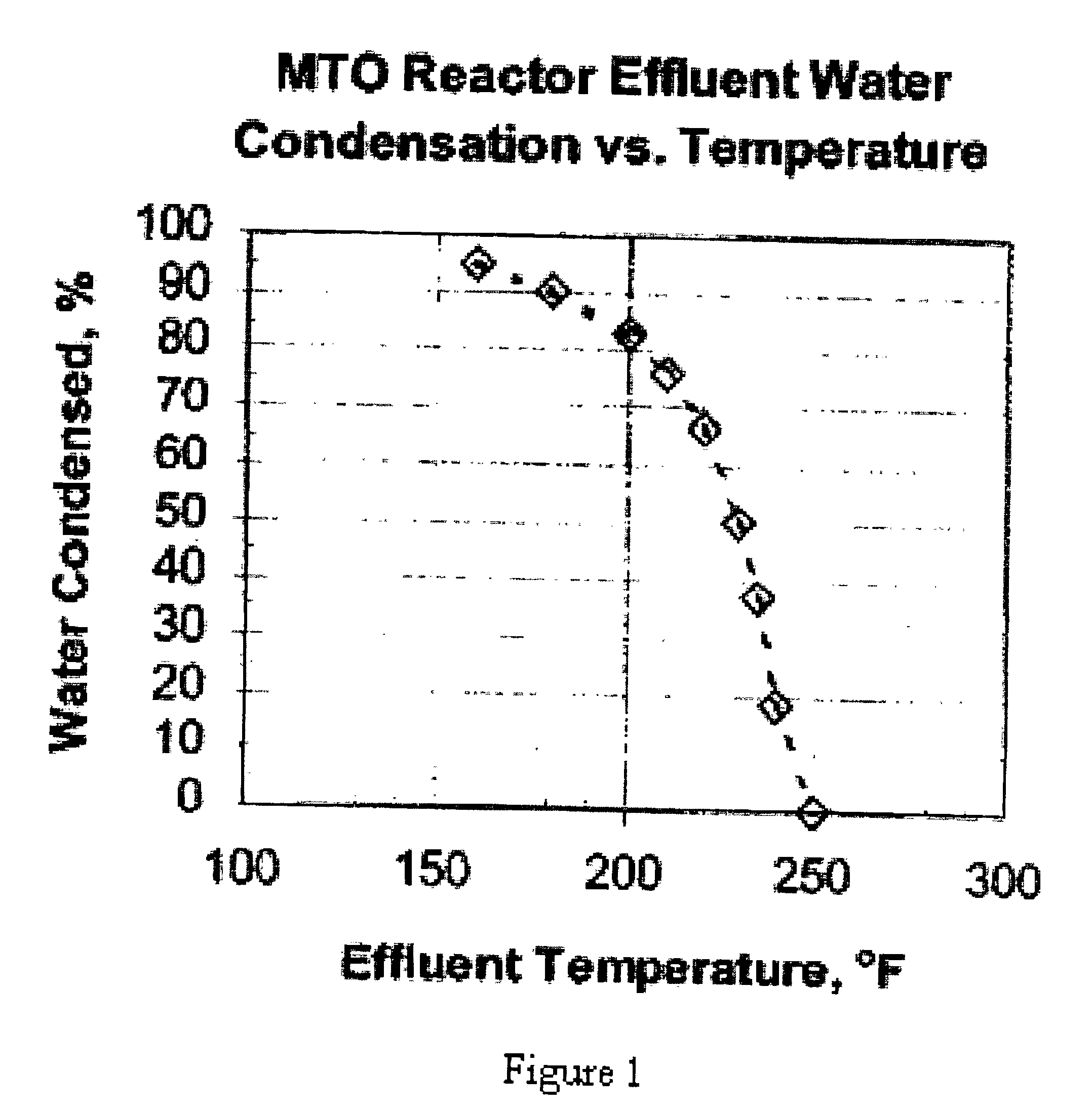
FIG. 1 shows the percent of condensed water in the effluent stream versus temperature at 40 psia (280 kPa).

In heat exchangers and other equipment downstream from the reactor prior to...

example 2

The gaseous effluent stream described in Table 1 is conveyed to a quench device at about 40 psia (280 kPa). FIG. 1 shows that with an OTO effluent stream given in Table 1, the condensation of water is prevented by keeping the temperature of the effluent stream above about 250° F. (120° C.) while it is being conveyed to a quench device. Therefore, the temperature of the effluent stream is dropped down to a temperature of 250° F. (120° C.) without mud forming in equipment prior to entering the quench device. The effluent stream then enters the quench device operating at a pressure of about 40 psia and is quenched to rapidly cool the effluent stream to 200° F. (93° C.) causing more than about 80% of the water in the effluent stream to condense. The catalyst fines leave the remaining gas phase of the effluent stream and enter the dilute liquid phase of the condensed water. Since there is a large amount of condensed water relative to the amount of catalyst fines, mud is not formed in the...


PUM

PropertyMeasurementUnit
wt %aaaaaaaaaa
wt %aaaaaaaaaa
wt %aaaaaaaaaa

Abstract

Disclosed is a process for recovering heat in an oxygenate to olefin (“OTO”) production process. The process includes removing heat while maintaining the temperature of an effluent stream that comprises solid particles (typically catalyst particles) and a gas phase comprising prime olefins from an OTO reactor above the dew point temperature of the effluent stream. The process further includes washing the effluent stream in solids wash to remove the solid particles from the gas phase into a liquid wash medium.

Description

FIELD OF THE INVENTIONThis invention relates to producing and recovering olefins from an oxygenate feed stream and more particularly to heat recovery in the process of producing and recovering olefins from an oxygenate feed stream.BACKGROUND OF THE INVENTIONPrime olefins, defined as ethylene and propylene and are materials that are used to make polyolefins. Specifically, ethylene and propylene are used to make polyethylene polypropylene respectively—two of the most commonly used plastics. These prime olefins are produced by taking larger hydrocarbons (e.g., C6 to C8 hydrocarbons) found in petroleum feed stream and subjecting it to steam cracking or catalytic cracking. Cracking processes break apart these larger hydrocarbons into smaller olefins including ethylene and propylene. However, the cracking process produces nitrogen and sulfur impurities that require expensive purification steps.Another process for producing higher olefins is the process known as an oxygenate to olefin proc...

Claims


Application Information

Patent Timeline
Patent Type & Authority Patents(United States)
IPC IPC(8): C07C1/00C07C1/20
CPCC07C1/20C07C11/02C07C2529/85Y10S585/911Y10S585/91Y02P30/20Y02P30/40
Inventor LUMGAIR, DAVID RBEECH, JAMES HARDING
Owner EXXONMOBIL CHEM PAT INC
Why Eureka
Try Eureka