Solar battery cell and manufacturing method thereof

a solar cell and battery technology, applied in the field of solar battery cells, can solve the problems of large number of processes required for formation of stacked structures, inability to inability to completely absorb sunlight in full wavelength, etc., and achieve excellent power-generating efficiency per unit area, high reliability, and the effect of increasing the scattering

Inactive Publication Date: 2005-03-22
SHARP KK
View PDF13 Cites 39 Cited by
  • Summary
  • Abstract
  • Description
  • Claims
  • Application Information

AI Technical Summary

Benefits of technology

In view of the current situations as described above, an object of the present invention is to provide a solar battery cell having a serial stacked structure which exhibits an excellent

Problems solved by technology

(ii) It is impossible to absorb the sunlight entirely in full wavelengths.
Even though generated, they have certain lifetimes and may be lost at once, before being taken out as electric energy.
With this method, however, a large number of processes are required for formation of the stacked structure.
In addition, it can handle only the substrates of a limited dimensional range, and the effective area of the power-generating regions within the substrate of the solar battery would be small.
Pinholes would be generated in the photoelectric conversion layer with such a wet process, and patterning would be difficult in the case of a substrate having a curved surface.
When the film thickness of the upper cell of the solar battery cell is increased, however, although the current values generated in the upper and lower cells may be balanced, such an increased film thickness of the upper cell would cause further degradation of light, thereby adversely decreasing the power-generating efficiency of the solar battery cell.
In the case of a stacked type solar battery cell having a transparent conductive film interposed between upper and lower cells, however, forming such a serial stacked structure by conventionally known patterning utilizing heating by laser irradiation (h

Method used


Image

  • Solar battery cell and manufacturing method thereof
  • Solar battery cell and manufacturing method thereof
  • Solar battery cell and manufacturing method thereof

Examples


example 1

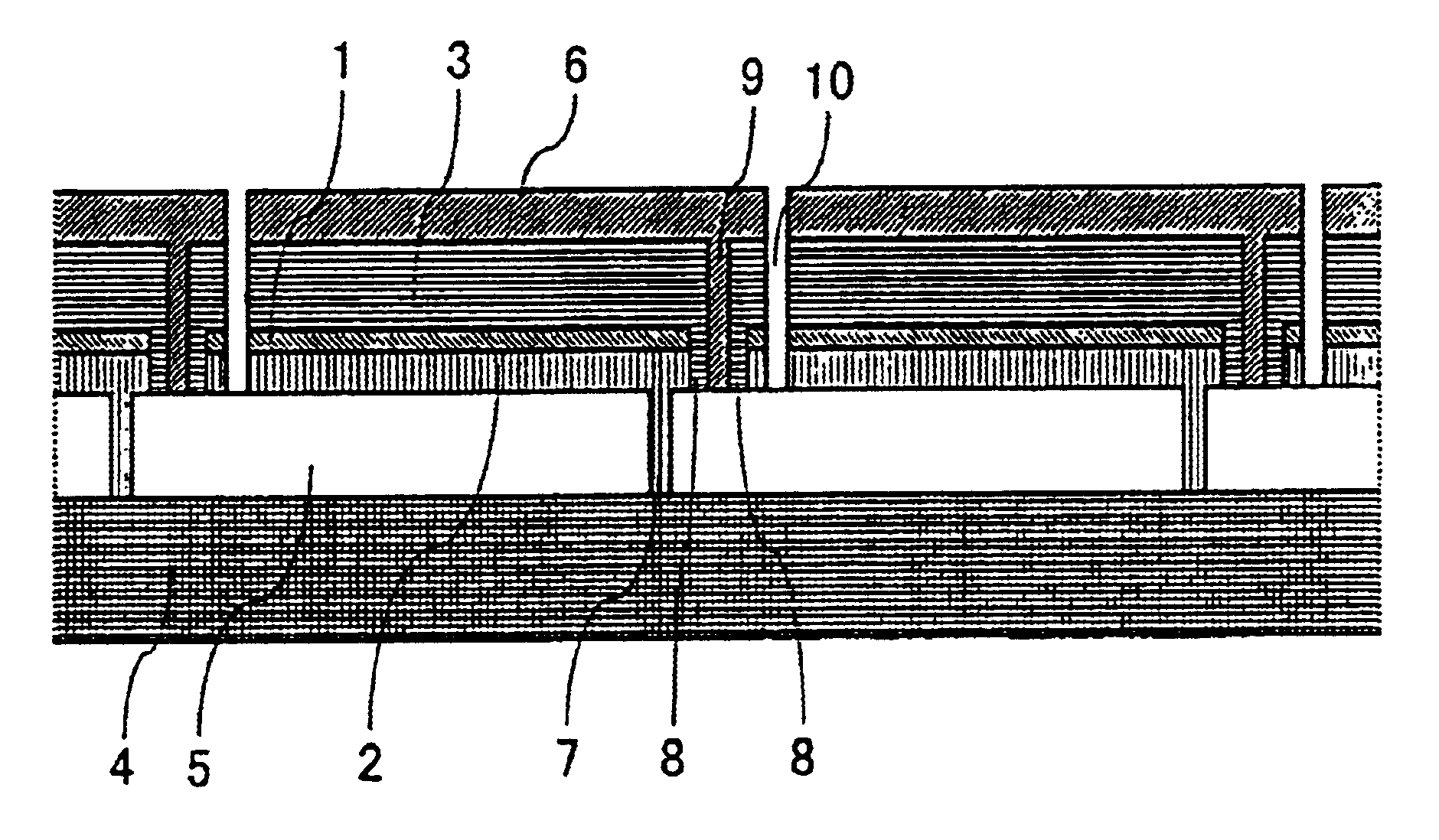
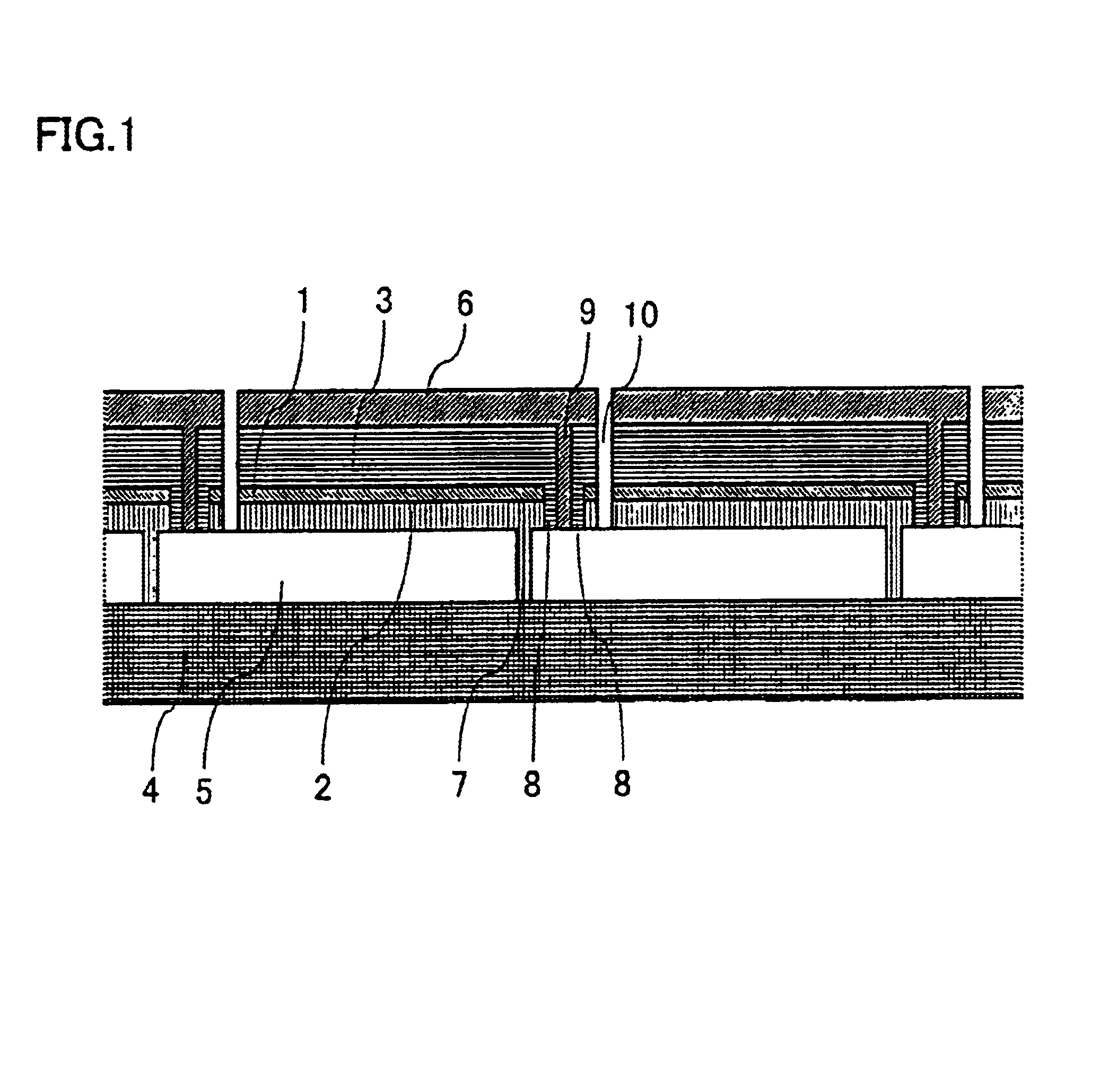
Example 1 is described with reference to FIG. 1. FIG. 1 shows a schematic cross section of the solar battery cell made in Example 1.

Firstly, a glass substrate having a thickness of about 4.0 mm and a substrate size of 650 mm×910 mm is prepared as an insulative transparent substrate 4. A transparent conductive film of SnO2 (tin oxide) is deposited on insulative transparent substrate 4 by thermal CVD, to form a front electrode 5.

Next, the fundamental wave of YAG laser is used to pattern front electrode 5. That is, laser beam is irradiated from the insulative transparent substrate 4 side to divide front electrode 5 into rectangular portions to form a front electrode separating line 7.

Thereafter, the substrate is subjected to ultrasonic cleaning with purified water. Semiconductor films are then stacked on front electrode 5 and filled inside front electrode separating line 7 by plasma CVD to form a photoelectric conversion layer as an upper cell 2. Upper cell 2 thus formed is the photoel...
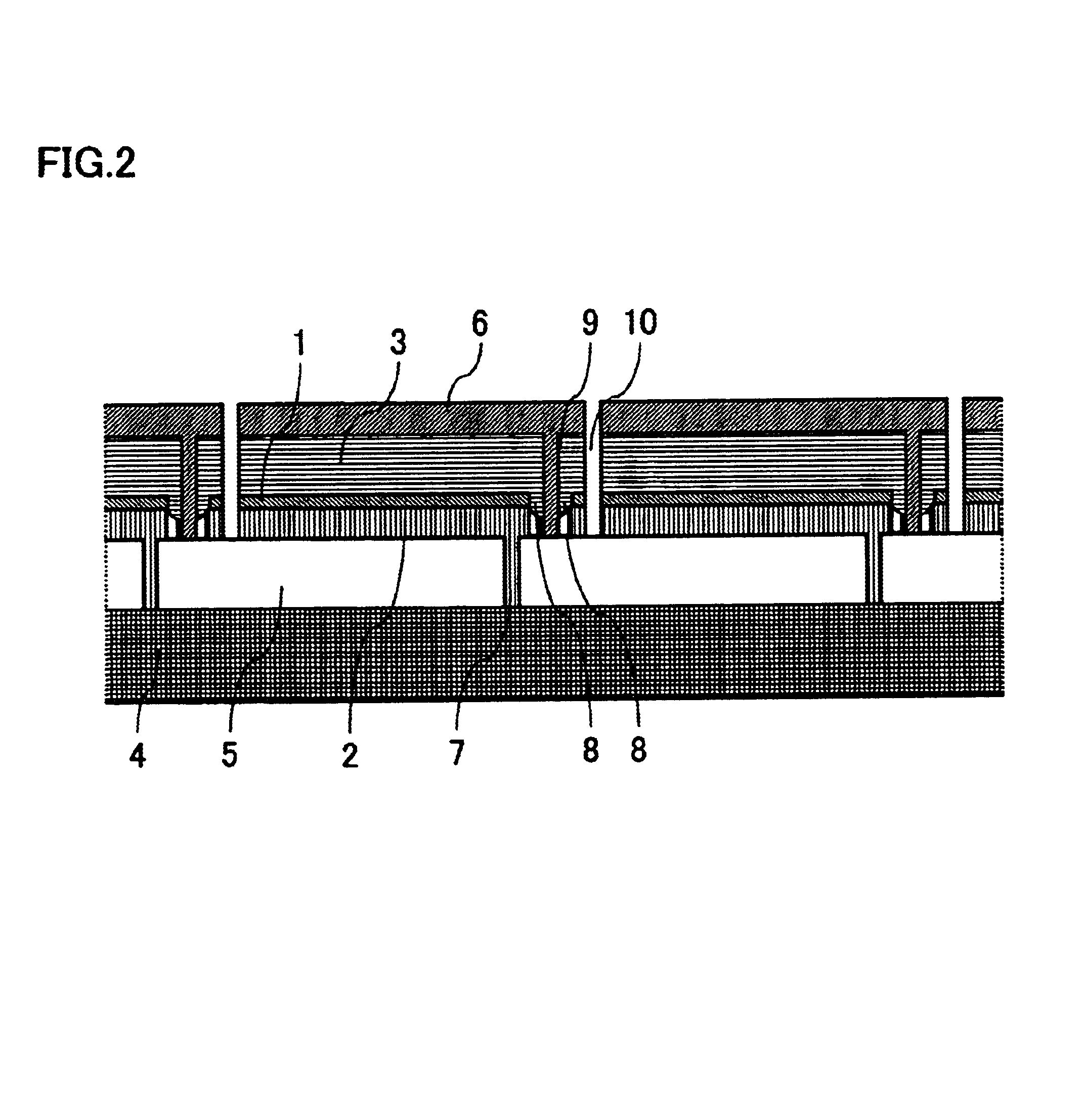
example 2

A solar battery cell was made in the same manner as in Example 1, except that the shape of intermediate transparent conductive film separating line 8 was changed to a curved surface. As a result, a solar battery cell (II) having the structure shown in FIG. 2 was obtained.

A solar simulator was used to carry out performance evaluation of the solar battery cell (II) thus obtained (substrate size: 650 mm×910 mm). The measurement results at AM 1.5 (100 mW / cm2) were Isc: 0.936A, Voc: 75.6 V, F.F.: 0.71, and Pmax: 50.2 W.


PUM


Abstract

A solar battery cell of a serial stacked structure, increasing scattering of light, exhibiting good power-generating efficiency per unit area, and ensuring high reliability and a large yield in the manufacturing process, is provided. The solar battery cell includes a plurality of power-generating regions connected in series, each having insulative transparent semiconductor, front electrode, intermediate transparent conductive film, photoelectric conversion layer formed of stacked semiconductor films, and back electrode, and a contact line electrically connecting the front electrode and the back electrode of the neighboring respective power-generating regions. One power-generating region has at least two photoelectric conversion layers with the intermediate transparent conductive films sandwiched therebetween. At least one member of nonconductor and/or semiconductor is provided between the intermediate transparent conductive film and the contact line to prevent direct contact thereof.

Description

BACKGROUND OF THE INVENTION1. Field of the InventionThe present invention relates to a solar battery cell. More particularly, the present invention relates to a solar battery cell having a plurality of power-generating regions connected in series, each power-generating region having an insulative transparent substrate, a front electrode, an intermediate transparent conductive film, a photoelectric conversion layer formed of stacked semiconductor films, and a back electrode.Further, the present invention relates to a manufacturing method of the solar battery cell as described above. More particularly, the present invention relates to a manufacturing method of the solar battery cell having a plurality of power-generating regions connected in series, each power-generating region having an insulative transparent substrate, a front electrode, an intermediate transparent conductive film, a photoelectric conversion layer formed of stacked semiconductor films, and a back electrode.2. Descri...

Claims


Application Information

Patent Timeline
IPC IPC(8): H01L25/00H01L31/042H01L31/05H01L31/04H01L27/142H01L31/0465H01L31/06H01L31/075H01L31/076
CPCH01L31/076H01L31/046Y02E10/548H01L31/0463
Inventor TACHIBANA, SHINSUKESANNOMIYA, HITOSHI
Owner SHARP KK
Why Eureka
Try Eureka