Illumination optimization for specific mask patterns

a mask pattern and optimization technology, applied in the field of microlithographic imaging, can solve the problems of poor contrast and end-of-line errors, and the cost of trial and error optimization of illumination configuration becomes very large, and achieve the effect of reducing a number of pitches

Inactive Publication Date: 2005-03-22
ASML NETHERLANDS BV
View PDF21 Cites 92 Cited by
  • Summary
  • Abstract
  • Description
  • Claims
  • Application Information

AI Technical Summary

Benefits of technology

According to a yet another aspect of the present invention there is provided a method of optimizing a selected mask design comprising:identifying critical features of the selected mask design;determining an optimized illumination pr

Problems solved by technology

Phase-shifted masks have been used in order to image features which are on the order of the imaging radiation's wavelength or smaller, since diffraction effects at these resolutions can cause poor contrast and end-of-line errors, among oth

Method used


Image

  • Illumination optimization for specific mask patterns
  • Illumination optimization for specific mask patterns
  • Illumination optimization for specific mask patterns

Examples


example 1

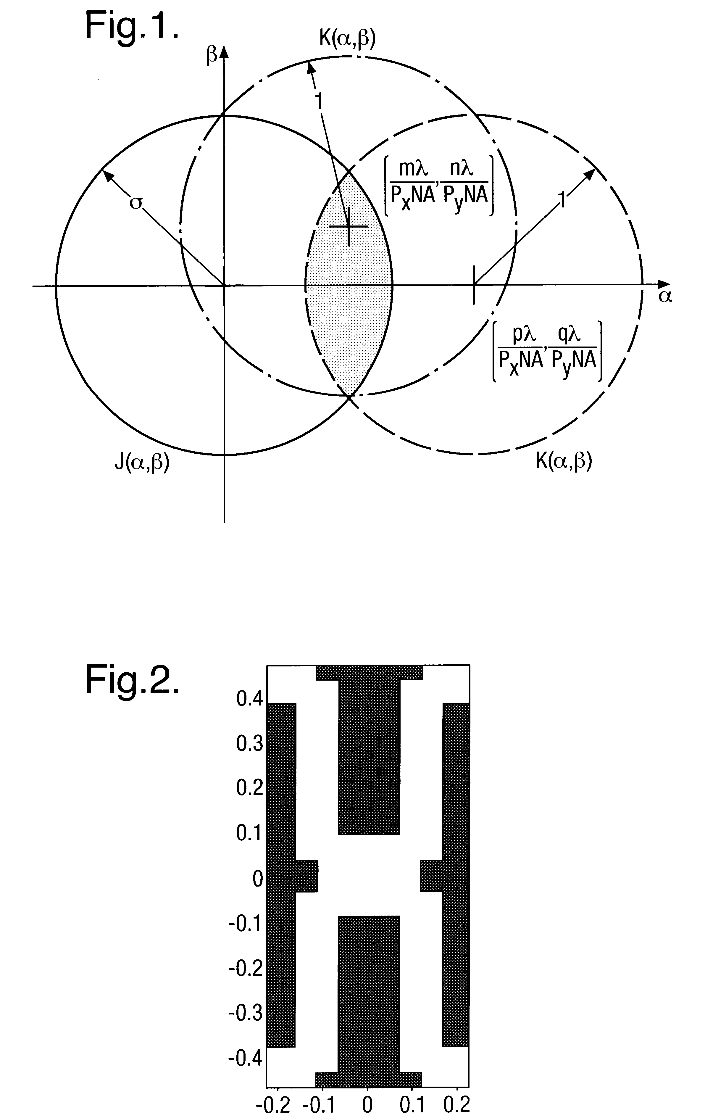
The technique for calculating Jtot outlined above was applied to a brick wall isolation pattern. A 150 nm pattern was shrunk to 130 nm and 110 nm design rules and imaged with a step and scan lithography system having a numerical aperture (NA) of 0.8. The isolation pattern for the 130 nm design rule is shown in FIG. 2.

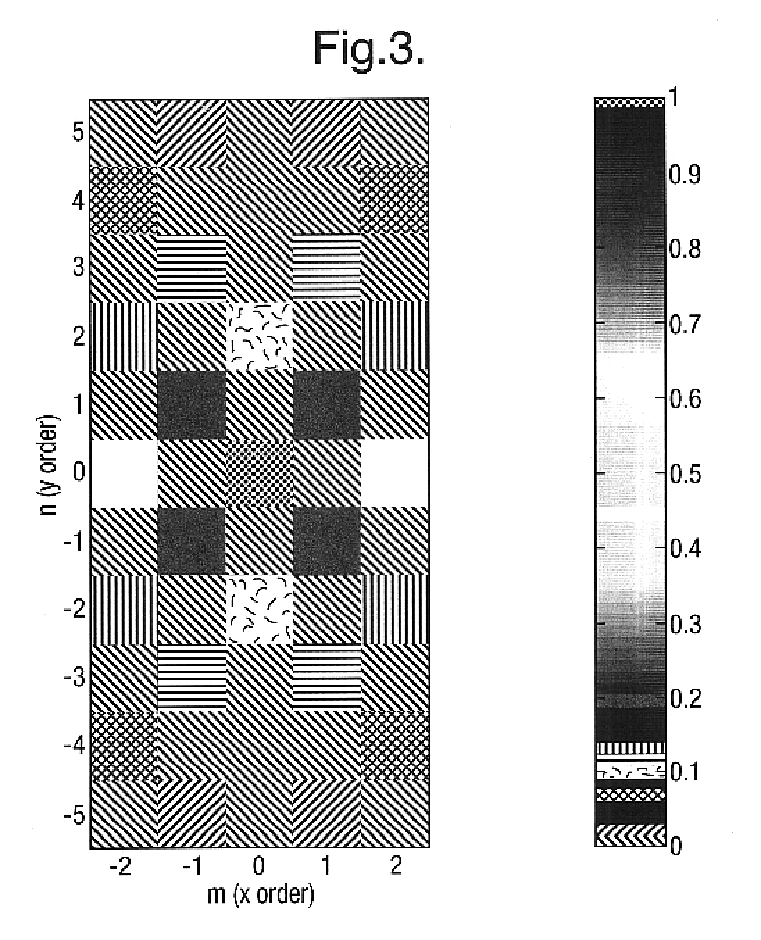
The magnitudes of the diffraction orders of this mask feature are plotted in FIG. 3. In FIG. 3, the largest order is the (0,0) order or the DC background light. The orders that contribute the most to imaging are the (±2,0) orders and represent the vertical bricks in the brick wall pattern. The other significant order is the (±1,±1) which represents the clear areas and defines the end of the isolation pattern. The higher orders also help to define two dimensional structures such as the end of each line. Since the diffraction orders are not constant, the orders change the weighting coefficients in the DOCC, which implies that the mask pattern influences the illumination s...

example 2

Using the gray scale to binary approach, a binary illumination configuration for the same brick wall isolation pattern was designed assuming a maximum outer σ of 0.88 and is shown in FIG. 6.

The performance of the optimized illumination configuration in FIG. 6 was then simulated for binary mask on a step and scan photolithography apparatus having NA=0.8 and λ=248 nm and compared to the simulated performance of annular illumination. In the simulation, the vector (thin-film) imaging resist model was used since the numerical aperture was above 0.7. In this model, the resist is 400 nm thickness of a type having a refractive index n=1.76−j0.0116), over 66 nm of another type having n=1.45−j0.3 on top of a polysilicon material having n=1.577−j3.588. The results with the annular illumination (σin=0.58 and of σout=0.88) and with the optimized illuminator (σout=0.88) are shown in FIGS. 7 and 8, respectively. In both FIGS. 7 and 8, cross section results in the middle of the isolation region and...

example 3

The results in FIGS. 7 and 8 for binary mask (BIM) were compared to simulation results for chromeless mask (CLM). A chromeless brick wall isolation pattern was designed from experimental results of software simulation in a manner known to those skilled in the art. The chromeless technology requires (0,0) order light so as to fully benefit from the DOF improvement produced by off axis illumination. Experimental results from the simulation confirm the need for (0,0) order light for which purpose the isolation layer should be dithered or half toned. The half tone pitch may be chosen such that the first order in the dithered direction does not fall into the projection pupil. In the example, the lines were dithered in the vertical direction with pitch less than λ / [NA(1+σout). The dithering duty cycle however should be tuned to optimize the amount of (0,0) order light for best DOF and pattern fidelity. In the simulation results for CLM the half tone pitch was 155 nm with 50% duty cycle (7...


PUM


Abstract

A method and apparatus for microlithography. The method and apparatus include optimizing illumination modes based on characteristics of a specific mask pattern. The illumination is optimized by determining an appropriate illumination mode based on diffraction orders of the reticle, and the autocorrelation of the projection optic. By elimination of parts of the illumination pattern which have no influence on modulation, excess DC light can be reduced, thereby improving depth of focus. Optimization of mask patterns includes addition of sub-resolution features to reduce pitches and discretize the probability density function of the space width.

Description

BACKGROUND OF THE INVENTION1. Field of the InventionThis invention relates generally to a method and apparatus for microlithographic imaging. More particularly, it relates to an apparatus and method for optimizing an illumination configuration according to the specific pattern being imaged.2. Background of the Related ArtOptical lithography systems are in current use in the manufacture of integrated circuits and other fine featured products such as programmable gate arrays. In a most general description, a lithography apparatus includes an illumination system which provides a projection beam of radiation, a support structure which holds a patterning structure, a substrate table which holds a substrate, and a projection system (lens) for imaging the patterned beam onto a target portion of the substrate.The term patterning structure should be broadly interpreted as referring to devices and structures that can be used to endow an incoming radiation beam with a patterned cross-section, ...

Claims


Application Information

Patent Timeline
IPC IPC(8): G03F7/20G03F1/14G03F1/00G03F1/36H01L21/027
CPCG03F1/144G03F1/36G03F7/70091G03F7/70433G03F7/70141G03F7/70425G03F7/70125G03F7/70441G03F7/705G03F7/20
Inventor SOCHA, ROBERT JOHN
Owner ASML NETHERLANDS BV
Why Eureka
Try Eureka