Nanomaterial processing system

a technology of nanomaterials and processing systems, applied in the field of nanotechnology, can solve the problem of relatively high equipment cos

Inactive Publication Date: 2005-03-29
YEU MING TAI CHEM INDAL +1
View PDF3 Cites 3 Cited by
  • Summary
  • Abstract
  • Description
  • Claims
  • Application Information

AI Technical Summary

Benefits of technology

The present invention has been accomplished under the circumstances in view. It is the main object of the present invention to provide a nanomaterial processing system, which is practical for processing nanomaterials. It is still another object of the present invention to provide a nanomaterial processing system, which is simple and cost-effective.
To achieve these and other objects of the present invention, the nanomaterial processing system comprises compressor means adapted to compress a flow of air/liquid into a high-pressure flow of air/liquid, the compressor means having an inlet for the input of the flow of air/liquid and an outlet for the output of the high-pressure flow of air/liquid; a material feeder adapted to feed a material into the high-pressure flow of air/liquid passing out of the outlet of the compressor means, enabling the fed material to be mixed with th...

Problems solved by technology

The equipment cost will be relatively hi...

Method used


Image

  • Nanomaterial processing system
  • Nanomaterial processing system
  • Nanomaterial processing system

Examples


first embodiment

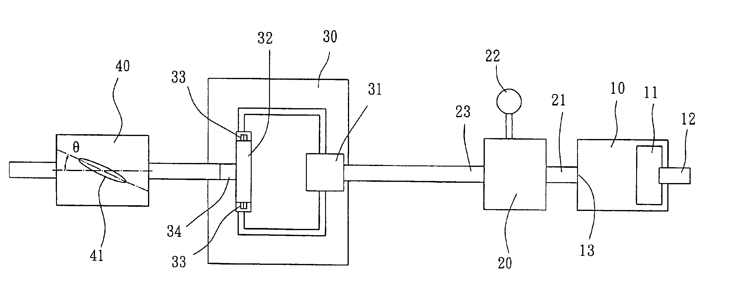
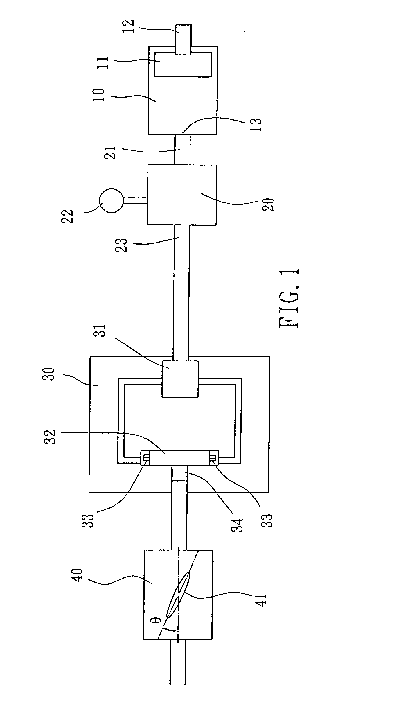
Referring to FIG. 1, a nanomaterial processing system in accordance with the present invention is shown comprised of a compressor 10, a material feeder 20, a shunt collider 30, and a high-speed cutting unit 40.

The compressor 10 can be an air compressor or fluid compressor. According to this embodiment, the compressor 10 is a fluid compressor adapted to add pressure to a fluid by means of a high R / R ratio compressing method. The output pressure value of the compressor 10 is about 20000˜25000 PSI. The compressor 10 has a liquid inlet 12 disposed at one end and mounted with a filter 11, and a liquid outlet 13 disposed at the other end.

The material feeder 20 has a first high-pressure pipe 21 extended from one end thereof and connected to the liquid outlet 13 of the compressor 10 and adapted to receive compressed fluid from the compressor 10 and to suck raw material into the intake flow of compressed fluid by means of high-pressure flow siphon effect, for enabling raw material to be mixe...

second embodiment

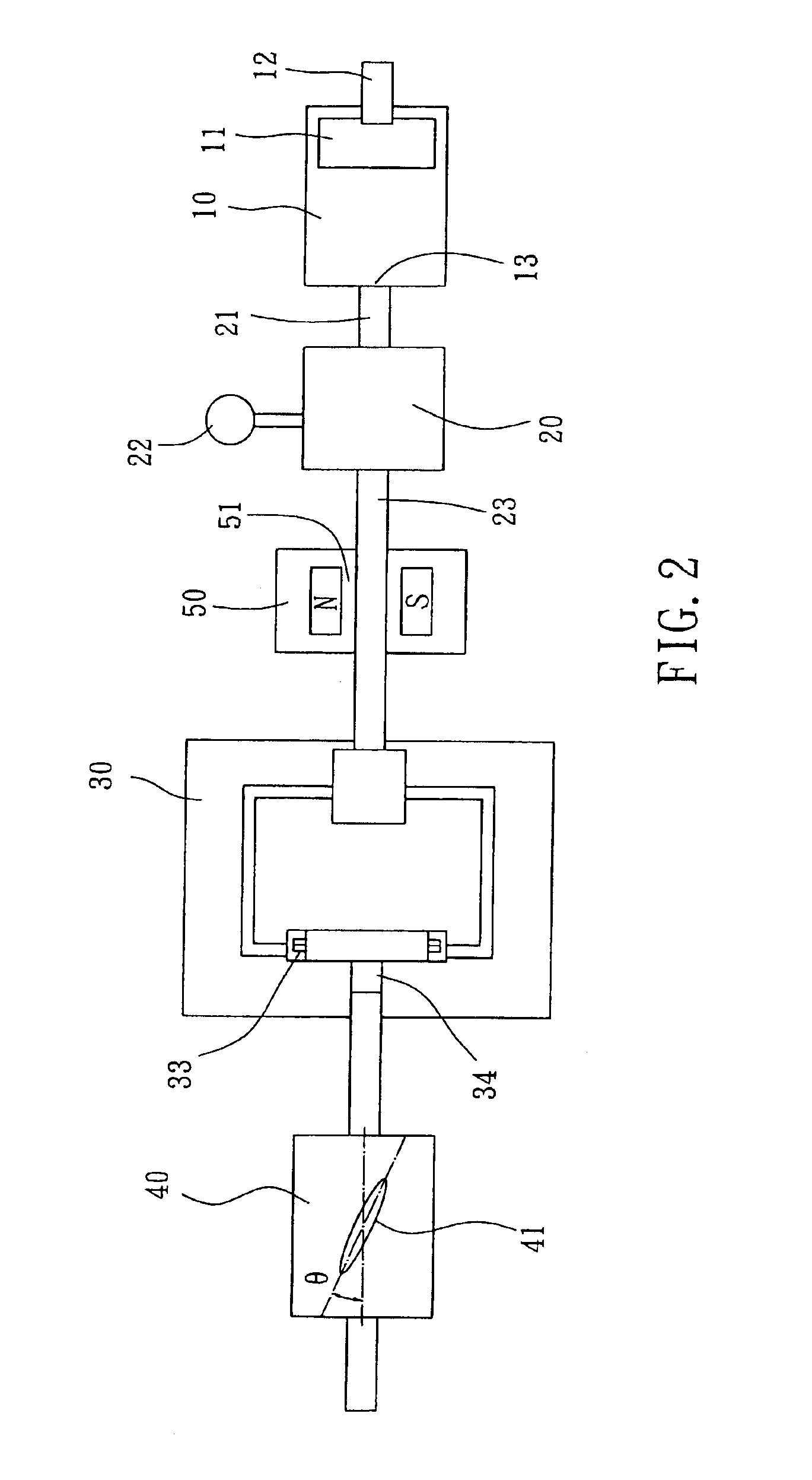
FIG. 2 is a block diagram of the nanomaterial processing system according to the present invention. According to this embodiment, a magnetizer 50 is installed in the second high-pressure pipe 23, and adapted to generate a magnetic field that magnetize the material flow passing through the second high-pressure pipe 23 to the shunt collider 30, causing group molecules of water to reduce from 100˜170 Hz to 50˜80 Hz and to facilitate further processing.

By means of the application of the simple, inexpensive nanomaterial processing system, materials can efficiently and economically processed into fine nanopowder.

third embodiment

FIG. 3 is a block diagram of the nanomaterial processing system according to the present invention. According to this embodiment, a gas source 50 is provided in front of the compressor 10, and adapted to add a suitable amount of inert gas, for example, helium or neon to the fluid passing through the compressor 10. The added inert gas protects the processed nanopowder against oxidation. Alternatively, another kind of gas, for example, ozone, deuterium or tritium may be added to the intake flow of fluid to change the physical properties of the material to be processed.

A prototype of nanomaterial processing system has been constructed with the features of FIGS. 1˜3. The nanomaterial processing system functions smoothly to provide all of the features discussed earlier.


PUM


Abstract

A nanomaterial processing system is constructed to include a compressor adapted to compress a flow of air/liquid into a high-pressure flow of air/liquid, a material feeder adapted to feed a material into the high-pressure flow of air/liquid passing out of the compressor, enabling the fed material to be mixed with the high-pressure flow of air/liquid into a high-pressure material flow; a shunt collider adapted to shunt the high-pressure material flow into two sub-flows and to let the shunt sub-flows to collide into a collided material flow, and a high-speed cutting unit, which uses a diamond coating-coated cutting wheel to cut solid substances the collided material flow.

Description

BACKGROUND OF THE INVENTION1. Field of the InventionThe present invention relates generally to nanotechnology and, more specifically, to a nanomaterial processing system for processing nanomaterials.2. Description of the Related ArtCurrently, the fabrication of nanomaterials commonly uses a nanopowder as base material, which is obtained by means of molecule collision, grinding, cutting or, or the application of an electric arc. Either molecule collision, grinding or liquid cutting, the particles of a nanopowder made according to the conventional methods have a certain size. For example, the particle size is about 20˜60 nanometers when made by means of molecule collision; or about 40˜120 nanometers when made by means of grinding. The equipment cost will be relatively higher when wishing to reduce the particle size.SUMMARY OF THE INVENTIONThe present invention has been accomplished under the circumstances in view. It is the main object of the present invention to provide a nanomateria...

Claims


Application Information

Patent Timeline
IPC IPC(8): B02C19/06
CPCB02C19/06B02C19/065Y10S977/89
Inventor TSAI, I-SHOULIAO, PEN-YICHOU, CHIN-CHUNKUO, WEN-IHUANG, LEI-TI
Owner YEU MING TAI CHEM INDAL
Why Eureka
Try Eureka