Biosensor, method of forming thin-film electrode, and method and apparatus for quantitative determination
a thin-film electrode and biosensor technology, applied in the field of biosensors, can solve the problems of difficult to make the uniform area of the working electrode, difficult to solve the described conventional biosensor z, and require an advanced printing technique, so as to improve convenience and safety.
- Summary
- Abstract
- Description
- Claims
- Application Information
AI Technical Summary
Benefits of technology
Problems solved by technology
Method used
Image
Examples
embodiment 1
A biosensor A as defined in the present invention will be described as a first embodiment with reference to the figures.
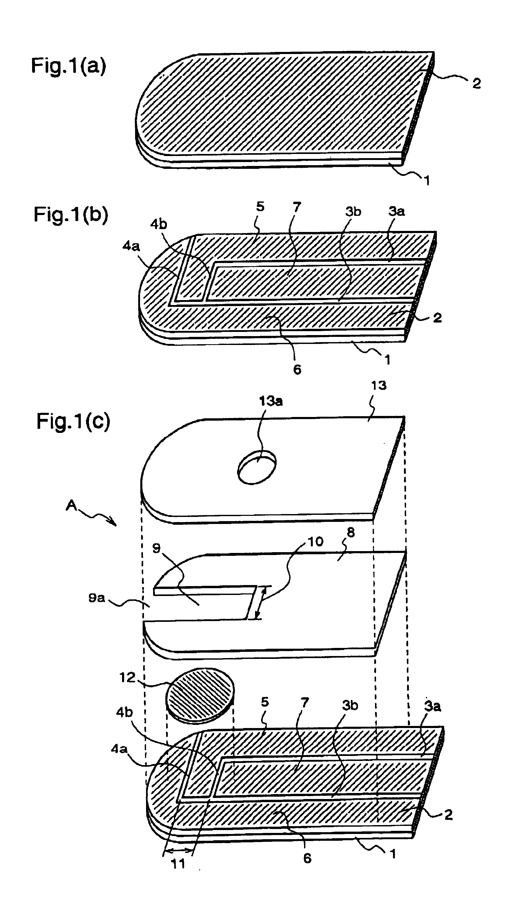
FIGS. 1(a) to 1(c) are exploded perspective views of the biosensor A according to the first embodiment of the present invention.
First, members constituting the biosensor A will be described.
Numeral 1 denotes a first insulating support (hereinafter, referred to as merely “support”) composed of polyethylene terephthalate or the like. Numeral 2 denotes a conductive layer which is formed on the whole surface of the support 1 and composed of an electrical conductive material such as a noble metal, for example gold or palladium, and carbon. Numerals 3a and 3b denote slits which are provided on the conductive layer 2 on the support 1 and are parallel to the side of the support 1. Numerals 4a and 4b denote slits which are provided on the conductive layer 2 on the support 1 and are vertical to the side of the support 1. Numerals 5, 6, and 7 denote a working electrode, a cou...
embodiment 2
A biosensor B according to of the present invention will be described as a second embodiment.
FIGS. 3 (a)-(c) are perspective views illustrating the biosensor B in the order of the manufacturing process, and FIG. 4 is a diagram illustrating a specimen supply path of the biosensor B.
First, the structure of the biosensor B will be described.
Numeral 21 denotes an insulating support which is composed of polyethylene terephthalate or the like. Numeral 22 denotes an electrical conductive layer which is formed on the whole surface of the support 21 and is composed of an electrical conductive material such as noble metal, for example gold or palladium, and carbon. Numerals 23a, 23b, 23c and 23d denote first slits which are provided on the electrical conductive layer 22. Numerals 25, 26 and 27 denote electrodes which are formed by dividing the electrical conductive layer 22 by the first slits 23a, 23b, 23c and 23d, i.e., a working electrode, a counter electrode, and a detecting electrode as a...
embodiment 3
A specific method for manufacturing the above-described biosensors A and B will be further described. Here, the biosensors A and B are assumed a biosensor X collectively.
FIG. 23 is a top view illustrating a state where the slits are formed on an electrical conductive layer provided on a surface of a sensor wafer P as a basis of the biosensor X.
Numeral 3102 denotes an electrical conductive layer composed of carbon, a metal material or the like, which is provided on the whole surface of a support 3101. Numerals 3103a, 3103b, 3103c and 3103d denote slits which are formed on the electrical conductive layer 3102. Numerals 3105, 3106 and 3107 denote electrodes which are formed by dividing the electrical conductive layer 3102 by the slits 3103a, 3103b, 3103c and 3103d, i.e., a working electrode, a counter electrode and a detecting electrode. Numeral 3110 denotes a cutting plane line showing a cutting position of the support. The sensor wafer P is a support in a state where the electrical c...
PUM
| Property | Measurement | Unit |
|---|---|---|
| Thickness | aaaaa | aaaaa |
| Thickness | aaaaa | aaaaa |
| Pressure | aaaaa | aaaaa |
Abstract
Description
Claims
Application Information
 - R&D
- Intellectual Property
- Life Sciences
- Materials
- Tech Scout
- Unparalleled Data Quality
- Higher Quality Content
- 60% Fewer Hallucinations
Browse by: Latest US Patents, China's latest patents, Technical Efficacy Thesaurus, Application Domain, Technology Topic, Popular Technical Reports.
© 2025 PatSnap. All rights reserved.Legal|Privacy policy|Modern Slavery Act Transparency Statement|Sitemap|About US| Contact US: help@patsnap.com


