Magnetic resonance imaging apparatus and method

a magnetic resonance imaging and apparatus technology, applied in the field of nuclear magnetic resonance imaging, can solve the problems of reducing image contrast or distorting images image may not be properly unfolded, etc., to reduce image artifacts, eliminate aliasing portions of images, and reduce image occurrence.

Inactive Publication Date: 2005-04-05
FUJIFILM HEALTHCARE CORP
View PDF5 Cites 31 Cited by
  • Summary
  • Abstract
  • Description
  • Claims
  • Application Information

AI Technical Summary

Benefits of technology

An object of the present invention is to more reduce occurrence of the artifacts of an image and to obtain an image having higher image quality in an MRI apparatus provided with a function for eliminating the aliasing portions of an image by executing a matrix calculation with respect to the signals obtained by a plurality of RF receiving coils.

Problems solved by technology

However, these sequence may decrease an image contrast or distort an image.
However, an image cannot be properly unfolded because the matrix calculation may be diverged depending on the positional relationship among the plurality of RF receiving coils used in the matrix calculation or a combination of the sensitivity distributions of the RF receiving coils.
For example, there is no difference in the sensitivity distributions among the RF receiving coils used in the matrix calculation, the image may not be properly unfolded because the matrix calculation is diverged.
Further, when the matrix calculation is executed while including the signal components of a low signal region such as a background and the like, an error may be increased by the affect of noise when aliasing portions are unfolded.
As a result, the SN ratio of an image having been unfolded may be extremely deteriorated or spot artifacts may occur in an image.
Further, even if the positional relationship among the RF receiving coils used in the matrix calculation is optimum with respect to a specific direction, there is a possibility that artifacts and deterioration in image quality may occur in a resultant image when a measuring axis and a measuring slice section are varied or when an encode axis is varied.
Further, when the number of channels of received signals is small, there is a case that images transformed from the sensitivity distributions of the respective RF receiving coils and images transformed from the sensitivity distribution of the entire body coil cannot be obtained simultaneously.

Method used


Image

  • Magnetic resonance imaging apparatus and method
  • Magnetic resonance imaging apparatus and method
  • Magnetic resonance imaging apparatus and method

Examples


first embodiment

(First Embodiment)

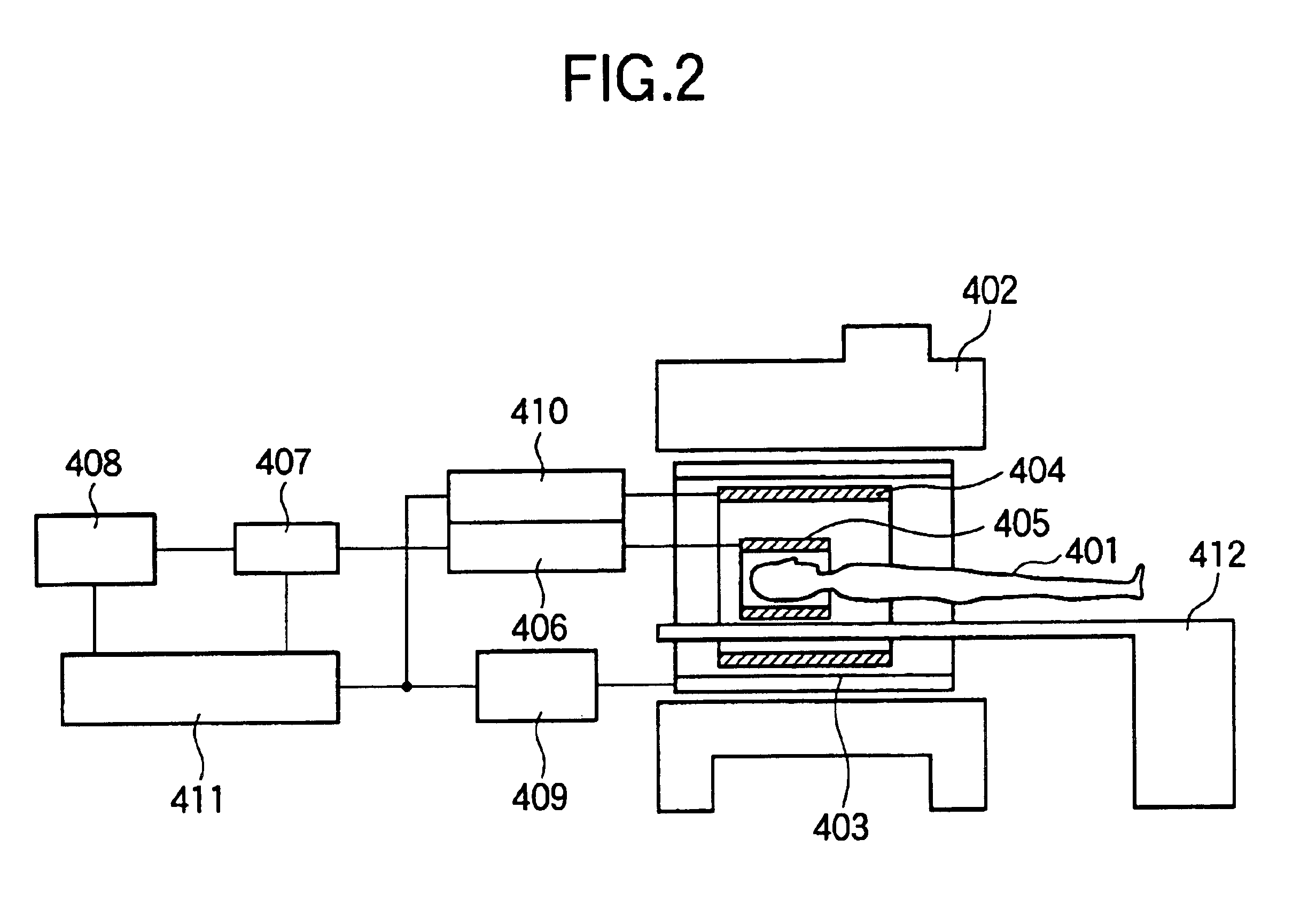
A first embodiment of the present invention will be explained with reference to FIGS. 1 to 10. As shown in FIG. 2, a typical MRI apparatus includes a magnet 402 for generating a static magnetic field in the space of a periphery including a patient 401, a gradient magnetic field coil 403 for generating gradient magnetic fields in the space, an RF transmission coil 404 for generating a radio-frequency magnetic field in the region, and an RF probe 405 for detecting the NMR signals generated by the patient 401. Although the figure shows an MRI apparatus having a vertical magnetic field in which a static magnetic field is generated in a vertical direction, a MRI apparatus having a horizontal magnetic field in which the static magnetic field is generated in the body axis direction of the patient 401 may be employed.

The gradient magnetic field coil 403 is composed of a plurality of coils for generating the gradient magnetic fields in X-, Y- and Z-directions and generate t...

second embodiment

(Second Embodiment)

Next, a second embodiment of the present invention will be described with respect to FIGS. 11 to 13. In the second embodiment, an example that four RF receiving coils are used as the multiple RF receiving coil different from the example shown in FIG. 3 will be explained. Accordingly, the second embodiment is arranged similarly to that of the first embodiment except that the receiving unit of the measured signals shown in FIG. 4 is arranged to have four channels. Further, since an MRI apparatus is the same as that of the first embodiment shown in FIG. 2 and a pulse sequence is the same as that of the first embodiment shown in FIG. 5, explanation of them is omitted.

An object to be measured, which is generally employed in MRI apparatuses at present, is protons that are a material mainly constituting a patient. The morphology or function of the head, belly, four limbs, and the like of a human body is two-dimensionally or three-dimensionally imaged by transforming the ...

third embodiment

(Third Embodiment)

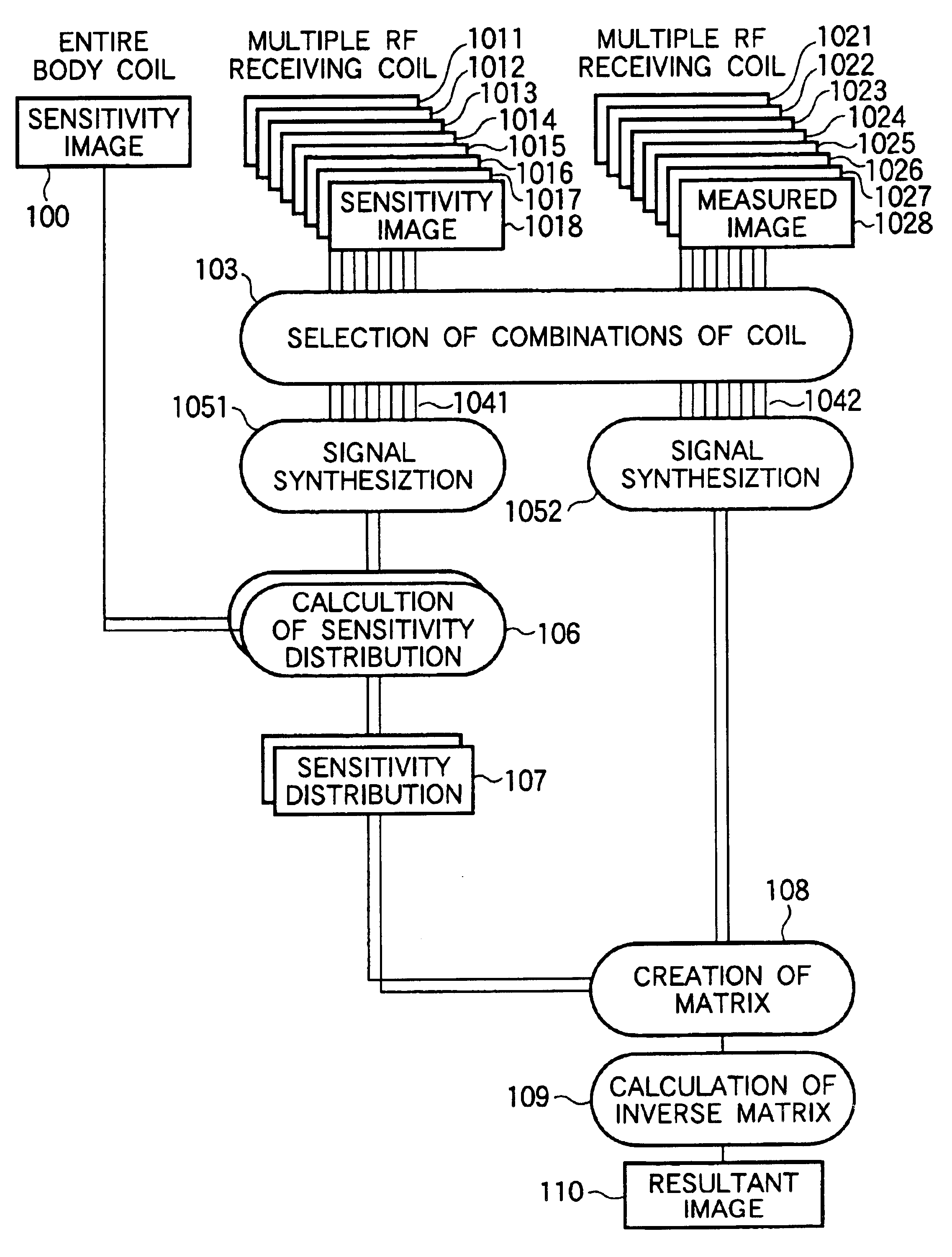
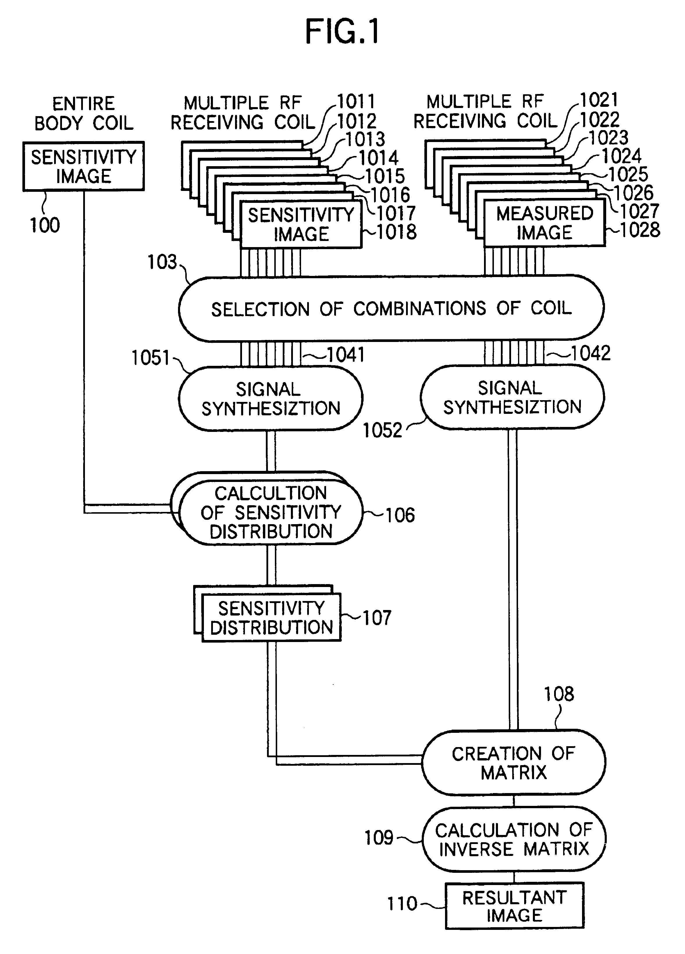
FIG. 13 shows a modification of the second embodiment. This embodiment shows a case that the sensitivity image of an entire body coil necessary to calculate the sensitivity distributions of respective RF receiving coils cannot be obtained. In this case, a pseudo image is created by signal coupling processing executed at step 801 in place of the sensitivity image of the entire body coil. In the signal coupling processing executed at step 801, images wi(x, y) are obtained by filtering, for example, the sensitivity images si(x, y) obtained by the respective RF receiving coils with a low-pass filter. Thus, it is possible to determine pseudo body coil images s′c (x, y) after they have been synthesized can be obtained by Expression (13). sc′⁡(x,y)=∑i-1N⁢ ⁢si⁡(x,y)·wi*(x,y)∑i-1N⁢ ⁢wi⁡(x,y)2(13)

where, * represents a complex conjugate, and | | represents an absolute value.

Incidentally, the RF receiving coils constituting a multiple RF receiving coil have a sensitive region ...


PUM


Abstract

A magnetic resonance imaging apparatus includes a magnetic field generation means for applying gradient magnetic fields and a radio-frequency magnetic field to a patient placed in a static magnetic field in a predetermined pulse sequence; a multiple RF receiving coil comprising at least three RF receiving coils for receiving the nuclear magnetic resonance signals generated from the patient; and an image reconstruction means for reconstructing an image by processing the received nuclear magnetic resonance signals, wherein the image reconstruction means includes a coil selection means for selecting a plurality of RF receiving coil groups that are preset by combining the plurality of RF receiving coils according to imaging conditions, a synthesization means for synthesizing the measured data received by the respective RF receiving coils of each of the plurality of selected RF receiving coil groups, and a calculation means for eliminating aliasing artifacts by executing a matrix calculation as to the synthesized data.

Description

TECHNICAL FIELDThe present invention relates generally to a nuclear magnetic resonance imaging (hereinafter, referred to as “MRI”) method and apparatus that measures nuclear magnetic resonance (hereinafter, referred to as “NMR”) signals from hydrogen and phosphorus in a patient and transforms the density distribution and the relaxation time distribution of nuclear spins into images. More particularly, the present invention relates to an MRI apparatus that uses a plurality of RF (radio-frequency) receiving coils and eliminates aliasing artifacts, which are generated when signals are obtained by the respective RF receiving coils thinning phase encodes, by a matrix calculation using the sensitivity distributions of the respective RF coils.BACKGROUND ARTAn MRI apparatus obtains echo signals necessary to reconstruction of a sheet of an image by repeatedly executing a pulse sequence (hereinafter, simply referred to as “sequence”) while varying an amount of phase encode. Accordingly, an im...

Claims


Application Information

Patent Timeline
Patent Type & Authority Patents(United States)
IPC IPC(8): G01R33/561G01R33/34G01R33/3415G01R33/54
CPCG01R33/5611G01R33/3415
Inventor TAKIZAWA, MASAHIROTAKAHASHI, TETSUHIKOOCHI, HISAAKITANIGUCHI, YO
Owner FUJIFILM HEALTHCARE CORP
Why Eureka
Try Eureka