Power saving automatic zoned dryer apparatus and method

a dryer and automatic technology, applied in the field of dryers, can solve the problems of unsatisfactory use of spray powder, rough printing surface of sheets, interference with good printing quality, etc., and achieve the effects of saving energy, and eliminating or greatly reducing the need for spray power

Inactive Publication Date: 2005-04-12
PRINTING RES
View PDF44 Cites 65 Cited by
  • Summary
  • Abstract
  • Description
  • Claims
  • Application Information

AI Technical Summary

Benefits of technology

The present invention saves energy. It eliminates or greatly reduces the need to use spray power. By drying under temperature control, independent separately controlled dryer zones create a more uniform temperature profile across the printed sheets without under or over drying some areas of the sheet. Better and more complete drying makes it possible to turn two pass printing jobs around and print again more quickly without waiting downtime. The risk of blocking is reduced because drying of all printed areas of the sheet is more uniform. Better moisture control in the printed sheets results in an improvement in sheet quality and better handling in subsequent operations. The invention should be considered broader than the preferred embodiment. The power saving automatic zoned dryer apparatus could be applied to any conveyor operation where articles to be dried are moved along a path, such as a conveyor for articles, parts or sheets that have been painted or lithographed.

Problems solved by technology

The use of spray powder is not desirable for other reasons.
It can cause a rough feel to the printed surfaces of sheets and builds up on plates and blankets where it can interfere with good printing quality.
This causes more frequent shutdowns to wash plates and blankets and is also detrimental to press components.
Although spray powder can prevent offsetting while the ink and / or coating dries, this is only a partial solution to drying problems at best.
For high speed press operation, for example, at 5,000 sheets per hour or more, good drying is not generally obtained by convection flow alone.
One of the problems with some prior art infra-red (IR) dryers is the fact that they must extend the fill width of the substrate width capacity of the press and they generally operate by off-on control.
This kind of prior art dryer will continue to apply power across the full 40 inch (102 cm) width with a corresponding waste of expensive electricity and generation of unnecessary heat in the press and the pressroom.
Importantly, none of the groups of lamps in this prior art design, nor any individual lamp, is independently controlled in response to the temperature of the sheet.
In addition, it is known that areas containing only text may require little or no drying whereas areas containing heavy coverage need considerably more drying power.
Although the cost of energy is high in this country, there are a number of foreign countries where electrical energy costs three to four times as much as it does here.
Despite attempts to moderate the effect of such intense radiation, temperature variation in the sheet continues to be a problem which is exacerbated when the sheets are stacked such that heat cannot readily escape and heat build up in the stack can occur.
Nonuniform temperature can affect moisture content and a tendency for curling of the sheets.
High temperature areas can increase the tendency for offsetting and sticking / blocking of sheets.
Temperature non-uniformity is believed to occur because the printed sheet has varying amounts of ink with different colors in different areas which absorb more or less infra-red radiant energy.
On the other hand, heavily printed areas with a dark color such as black, may readily absorb greater quantities of infra-red heat energy thus raising the temperature of the sheet nonuniformly.

Method used


Image

  • Power saving automatic zoned dryer apparatus and method
  • Power saving automatic zoned dryer apparatus and method
  • Power saving automatic zoned dryer apparatus and method

Examples


Embodiment Construction

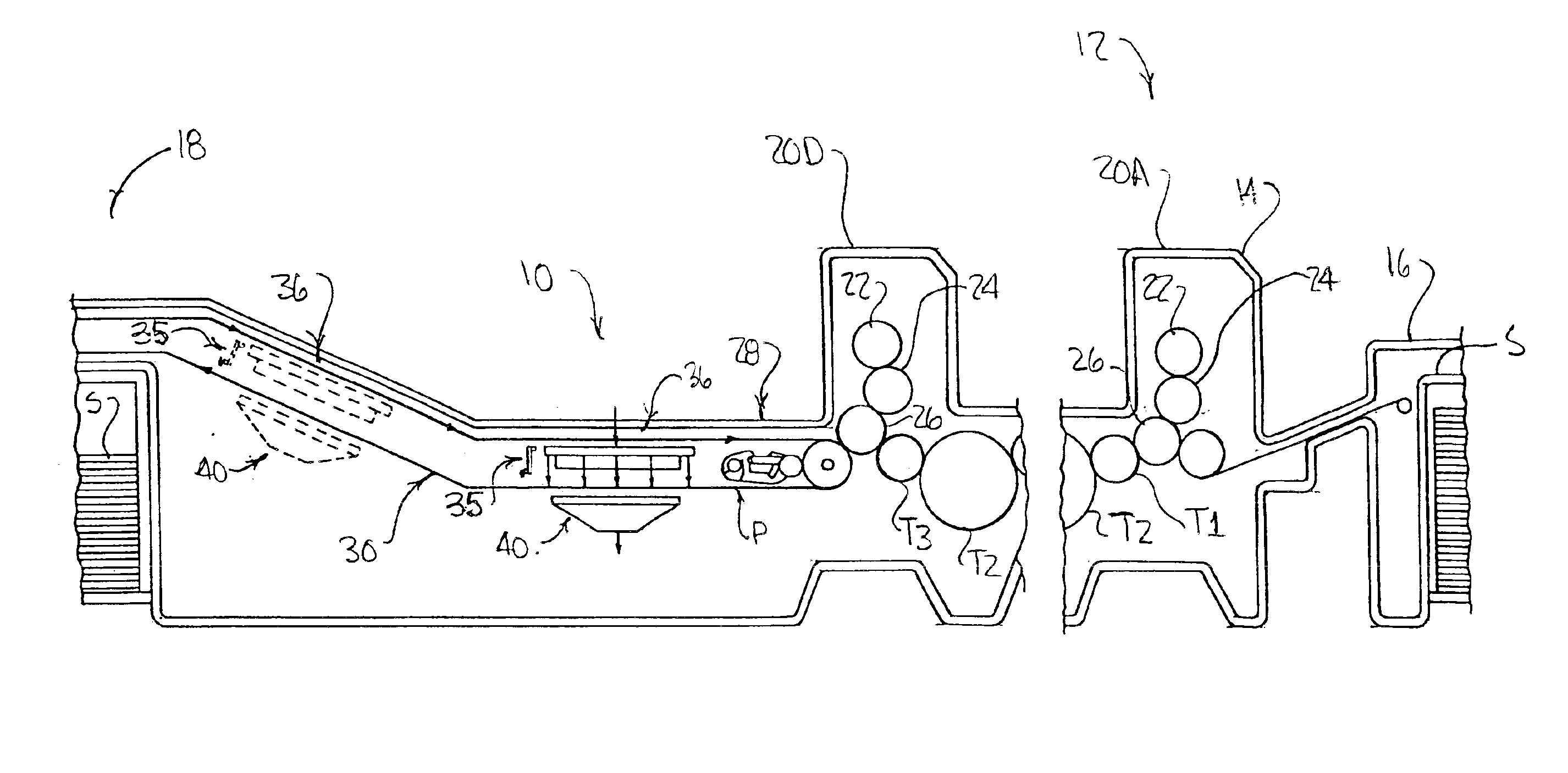
As used herein, the term substrate refers to printed sheets or printed web stock. The term heated area refers to an area on the substrate heated by an individual zone and may also be referred to as a band, an imaginary band or a heated band. The heated areas run the full length of the sheet in the longitudinal direction of the press and are segmented laterally as individual bands or strips lying adjacent to each other across the width of the substrate. Enough heating zones should be provided to cover the full width of the substrate.

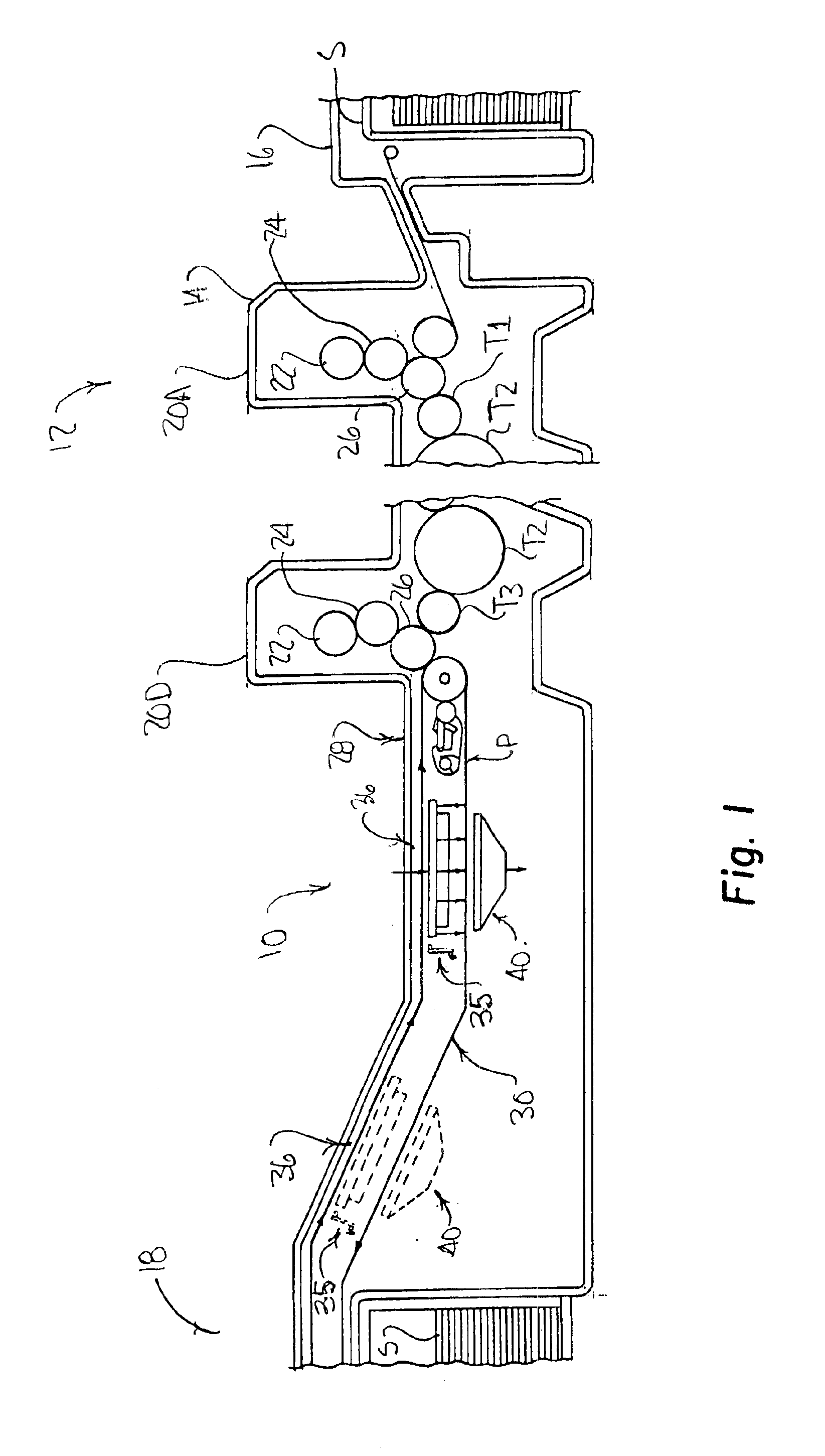
Referring now to FIG. 1, the dryer assembly 10 of the present invention will be described as being used for drying freshly printed substrates, either sheets or web stock, which have a protective and / or decorative coating or printing which has been applied in a sheet-fed or web-fed, rotary offset, rotogravure, flexographic printing press or even in digital printing. In this instance, dryer 10 of the present invention is mounted on the guide rails of the de...


PUM


Abstract

A computer controlled power saving automatic zoned dryer for a printing press has a dryer head facing the substrate travel path, having a multiplicity of IR lamps connected individually or in groups to form a plurality of heating zones running longitudinally and each extending laterally side by side across the substrate travel path. The radiant heat output of each heating zone is controlled separately by means of a control unit connected to a power supply. The control unit individually regulates output of the heating zones. Unneeded zones are turned off to reduce cost of power and conserve energy. A plurality of heat sensors spaced laterally across the substrate path measure the surface temperature of substrate heated areas corresponding to the heating zones being operated and maintain an automatic set point temperature. The temperature of each individual heated area can be regulated automatically by adjusting the output of its heating zone whereby printed substrates having a more even temperature profile are delivered. In an alternate manual mode any zone can be set independently to operate at any percentage of full available power from zero to 100%. Separate high velocity air scrubbers and additional air extraction are used to enhance the total drying effect of the zoned dryer assembly.

Description

FIELD OF THE INVENTIONThe invention lies in the field of dryers for printing presses which operate to regulate temperature of printed substrate sheets with differing ink coverage.BACKGROUND OF THE ARTRotary offset printing presses reproduce an image on a substrate comprising successive sheets of paper or a web of paper by means of a plate cylinder which carries the image, a blanket cylinder which has an ink transfer surface for receiving the inked image, and an impression cylinder which presses the paper against the blanket cylinder so that the inked image is transferred to the paper. Lithographic inks applied to the paper can be partly absorbed and dry mainly by oxidation. Such inks are strong relative to other inks, do not contain aqueous solvents and generally have a very high solids content. Drying of lithographic inks can be enhanced by oxidation at somewhat elevated temperatures.Many modern presses employ a coating or “lacquer” unit at the end of the press which can employ fle...

Claims


Application Information

Patent Timeline
Patent Type & Authority Patents(United States)
IPC IPC(8): B41F23/00B41F23/04F26B3/00F26B3/28F26B3/30F26B13/04F26B21/00F26B23/04F26B25/00
CPCF26B3/283B41F23/0443
Inventor DEMOORE, HOWARD W.
Owner PRINTING RES
Why Eureka
Try Eureka